Commands for writing and reading the data carrier, 1 write operation – EUCHNER CIS3(A) User Manual
Page 10
EUCHNER
Identsystem
CIS3
071652-01-8/99
Subject to technical modifications
page 10 / 23
5. Commands for writing and reading the data carrier
Read and write operations are always initiated by the higher-level control
(NC, PLC) with a "command telegram".
The read/write head then sends a response telegram to the control.
Control
Read/write head CIT3SX...
Command telegram
→
Response telegram
←
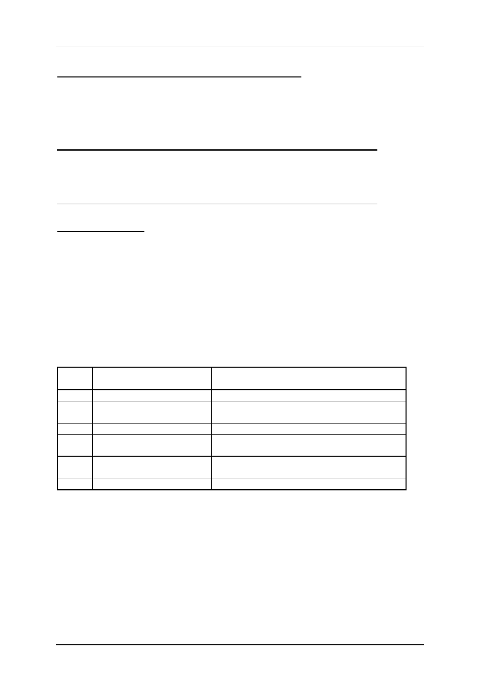
5.1 Write operation
The data carrier must be in front of the read/write head in the case of this command and
may be removed from the active area only after reception of the response telegram.
Command telegram (telegram core, PLC
→ CIT3SX , see also Figure 5):
TP (read/write head address) (start address) (number of Bytes user data) (user data)
Response telegram (telegram core, CIT3SX
→ PLC, see also Figure 6):
RF (read/write head address) (0.0) (Error No.)
Content or possible value range
Byte
No.
Description
ASCII
C O N T E N T S
HEX
Decimal
0
Number of telegram Bytes
8 ... 23
1
2
Command
identification
T
P
54
50
84
80
3
Read/write head address *)
01
01
4
5
Start address of the
user data
00
0 ... 5Fh
00
0 ... 95
6
Number of Bytes of the
user data
1 ... 10h
1 ... 16
7 ... 22 User data
ASCII or HEX resp. BCD (code-transparent) **)
Figure 5: Command telegram "Write data carrier" (telegram core)
*)
For downward compatibility with the CIS2 identification system.
The content of the header address must always be 1 in the case of CIS3.
**)
If read/write head CIT3SX.. is used in conjunction with read head
CIT3PL, please note that a Byte comprises 2 BCD digits (0 ... 9) when
programming the user data.