Figure 2: wiring diagram cms-e-er – EUCHNER CMS-E-ER User Manual
Page 8
Operating Instructions Safety Switch Evaluation Units CMS-E-ER
EUCHNER GmbH + Co. KG Kohlhammerstraße 16 D-70771 Leinfelden-Echterdingen Tel. +49 711 7597-0 Fax +49 711 753316 [email protected] www.euchner.de
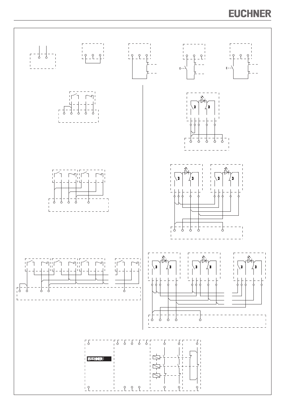
Figure 2: Wiring diagram CMS-E-ER
The following applies to all the illustrations:
f
Evaluation unit electrically isolated
f
Actuator not in the operating distance
Y3
Leseköpfe/read heads
1-2
13
14
Rückführkreis/
feedback loop
23
24
Sicherheits-
kontakte/
safety
contacts
Hilfs-
kontakt/
auxiliary
contacts
H12
H73
H11
0V
A2
UB
A1
H74
31
32
H22
Y1
Y2
CMS
Wiring diagram CMS-E-ER
Wiring diagram for one read head CMS-R-...
H12
H73
H11
H74
H22
BN
WH
1 Lesekopf/1 read head
BU
BK
Wiring diagram for one read head CMS-RH-...
H12
H73
H11
H74
H22
Lesekopf/read head
WH
BN
+
BU
BK
-
PK
1 2 3
4
5
1 Lesekopf/1 read head
Wiring diagram for 2 read heads CMS-R-...
H12
H73
H11
H74
H22
WH
BN
BN
WH
2 Leseköpfe/2 read heads
Lesekopf 1/
read head 1
Lesekopf 2/
read head 1
BU
BK
BU
BK
Wiring diagram for 2 read heads CMS-RH-...
H12
H73
H11
H74
H22
Lesekopf 1/read head 1
WH
BN
+
BU
BK
-
PK
Lesekopf 2/read head 2
WH
BN
+
BU
BK
-
PK
1 2 3
4
5
6 7 8
9
10
2 Leseköpfe/2 read heads
Wiring diagram for > 2 up to 30 read heads CMS-R-...
BK
BU
BK
H12
H73
H11
H22
WH
BN
BN
WH
H74
WH
BN
WH
BN
>2 bis 30 Leseköpfe/>2 up to 30 read heads
Lesekopf 1/
read head 1
Lesekopf 2/
read head 2
Lesekopf 3/
read head 3
Lesekopf n/
read head n
...
BU
BK
BU
BK
BU
Wiring diagram for > 2 up to 30 read heads CMS-RH-...
H12
H73
H11
H74
H22
Lesekopf 1/read head 1
WH
BN
+
BU
BK
-
PK
Lesekopf 2/read head 2
WH
BN
+
BU
BK
-
PK
Lesekopf n/read head n
WH
BN
+
BU
BK
-
PK
...
1 2 3
4
5
6 7 8
9
10
11 12 13
14
15
>2 bis 30 Leseköpfe/>2 up to 30 read heads
Operating voltage connection
Betriebsspannung/
operating voltage
A2
A1
UB
0V
Connection for automatic start
without feedback loop
Rückführkreis
feedback loop
Y1
Y2
Y3
Manual start using start button
with falling edge and
connected feedback loop
Rückführkreis/
feedback loop
Y1
Y2
Y3
Manual start using start button
with rising edge and
connected feedback loop
Rückführkreis/
feedback loop
Y1
Y2
Y3
Connection for automatic start
with feedback loop
Rückführkreis/
feedback loop
Y1
Y2
Y3