Technical data, Combination options – EUCHNER CMS-E-ER User Manual
Page 7
Operating Instructions Safety Switch Evaluation Units CMS-E-ER
Technical data
Parameter
Value
Unit
Housing material
Polyamide PA6.6
Dimensions
114 x 99 x 22.5
mm
Weight
0.22
kg
Ambient temperature
0 ... +55
°C
Storage temperature
-25 ... +70
°C
Degree of protection
according to EN 60529
Terminals IP20 / Housing IP40
Degree of contamination
2
Mounting
35-mm mounting rail acc. to DIN EN 60715 TH35
Connection
Connection terminals
Operating voltage U
B
24 ±10%
V AC/DC
Internal fuse (operating voltage U
B
)
750 (automatically resetting fuse PTC)
mA
Safety contacts
2 NO contacts
Switching voltage U
max.
240
V AC
Current consumption at DC 24 V
10 ... 110
mA
Switching current I
max.
at 24 V
3
A
Switching current, I
min.
at 24 V
10
mA
Breaking capacity P
max.
720
VA
External contact fuse (safety circuit)
acc. to EN IEC 60269-1
4
A gG
Auxiliary contact
1 NC contact
Switching current I
max.
at DC 24 V
1.5
A
Utilization category
I
e
1)
U
e
1)
According to EN 60947-5-1 AC-1
3 A
230 V
AC-1
3 A
24 V
AC-15
0.9 A
240 V
AC-15
0.9 A
24 V
DC-13
1.5 A
24 V
Switching load acc. to UL Class 2
Input:
24 V
AC/DC
Output:
30 V
AC
24 V
DC
Rated insulation voltage U
i
250
V
Vibration resistance
According to EN 60947-5-2
Mechanical operating cycles relays
10
7
EMC compliance
According to EN 60947-5-3
Approval
TÜV, UL
LED indicators
See drawing
Risk time according to EN 60947-5-3
20
ms
Reliability values acc. to EN ISO 13849-1
as a function of the switching current
at 24 V DC
≤
0.1
≤
1
A
Number of switching cycles/year
< 166,000
< 70,000
Mission time
20
years
Category
1 read head
4
>1 read head
3
Performance Level (PL)
1 read head
e
>1 read head
d
PFH
d
1 read head
2.5 x 10
--8
>1 read head
1.0 x 10
-7
1) I
e
= max. switching current per contact, U
e
= switching voltage
Combination options
Design
Read head
Circuit
diagram not
actuated
2)
Actuator
Assured
switch-on
distance s
ao
[mm]
3)
Assured
switch-off
distance s
ar
[mm]
Evaluation unit CMS-E-ER
CMS-R-AXH/-SC
4)
BN
WH
BK (YE)
BU (GN)
1
2
4
3
CMS-M-AC
6
31
CMS-R-BXI/-SC
CMS-M-BD
3
12
M25
CMS-R-CXC/-SC
CMS-M-CA
6
14
M30
CMS-R-EXM/-SC
CMS-M-EF
6
17
CMS-RH-AYA-...L
BN +
PK
WH
BU
BK -
GY NC
CMS-MH-AA
10
20
CMS-RH-BYB-...L
CMS-MH-BB
6
13
2) Old conductor coloring in brackets.
3) There must be no ferromagnetic material in the vicinity of the read head or the actuator.
All data refer to the frontal approach direction and a center offset of m = 0.
4) The minimum switching distance S
omin
between read head and actuator is 1 mm. If the distance is
less than this, the evaluation unit changes to the fault state.
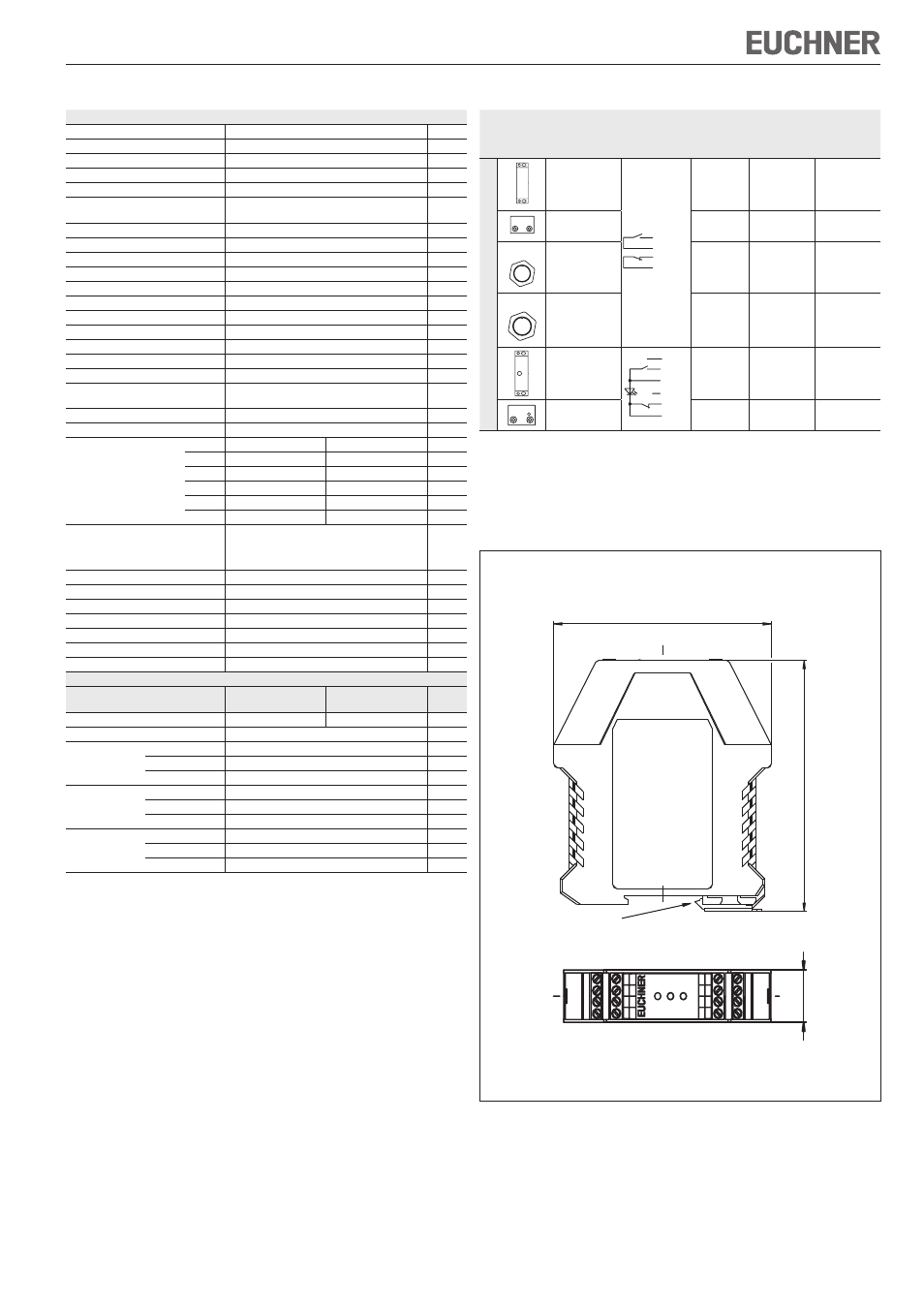
Figure 1: Dimension drawing evaluation unit CMS-E-ER
99
11
4
22,5
K2
K1
Powe
r
Safety Switch CMS
14
32
Y1
Y2
Y3
23
13
31
A2
24
H1
2
H7
4
H7
3
H2
2
H1
1
A1
Suitable for 35-mm mounting rail acc. to DIN EN 60715 TH35