Connecting ar switch chain, And 0v – EUCHNER CES-AR-AES-12 User Manual
Page 9
Operating Instructions AR Evaluation Unit CES-AR-AES-12
9
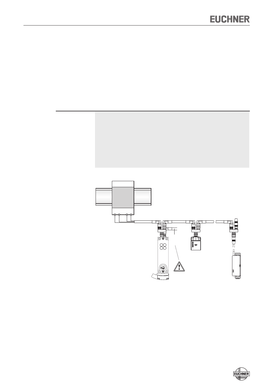
Connecting AR switch chain
The AR evaluation unit has two safety inputs to which the AR switch chain is con-
nected. Safety inputs IA and IB have short circuit and earth fault monitoring.
The AR switch chain must be supplied by the AR evaluation unit (terminals UB
AR
and
0V
AR
). An additional power supply may be required for these safety switches (e.g.
for guard locking), depending on which safety switches are used in the AR switch
chain (see Figure 5). In case of switches with guard locking, the supply for the
guard locking solenoid must be at the potential of the AR evaluation unit. Informa-
tion on this is provided in the operating instructions of the respective safety switch.
Important!
A maximum of 12 safety switches can be connected.
Only safety switches that are suitable for operation in an AR switch chain can
be connected.
Safety switches with start input are not suitable for connection to an AR evalu-
ation unit.
In the case Unicode switches, the actuators must be taught-in at the read head.
See the operating instructions for the related safety switch.
For the AR system to function, a bridging plug must be connected to the first
safety switch in the AR switch chain (or a jumper between IA, IB and UB
AR
).
Fig. 3: Schematic diagram showing connection of an AR switch chain
CES-AR-AES
UB
AR
IB
0V
AR
IA
CET-AR # n
CES-AR-C01 # n-1
CES-AR-C.2 # 1
STATE
DIA
Connection for
guard locking
solenoid
Use common ground potential
for AR evaluation unit and opera-
tion of the solenoid!
See Connection example on
page 14.