EUCHNER CET-AX User Manual
Page 4
Operating Instructions Read Head CET-AX with Guard Locking and Guard Locking Monitoring
EUCHNER GmbH + Co. KG Kohlhammerstraße 16 D-70771 Leinfelden-Echterdingen Tel. +49/711/75 97-0 Fax +49/711/75 33 16 www.euchner.de [email protected]
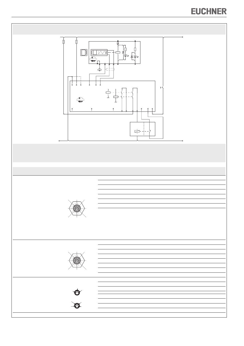
Figure 4: Connection example and terminal assignment
24 VDC
GND
-F1
0V
TST
-F2
UB
CES-AZ-AES-01B
104770
J
SH1
O1
H11H12
EUCHNER
DIA
23 24
13 14
Y1
Y2 S
Start
K2
+
K1
+
A
ct
ua
to
r
Re
ad
-
he
ad
CET1-AX-LRA-00-50X-SA
095735
3
2
1
6
7
LED1
4
LED2
5
UCM
0V UCM
LED2
0V
-S1
8
EUCHNER
Feed-
back
loop
Connected
load
Read head
Plug connector
(view of connection side)
PIN
Function
Wire color
Connection cable*
CET1-AX-LRA-00-50X-SA
095735
CET2-AX-LRA-00-50X-SA
106039
CET1-AX-LDA-00-50X-SE
100399
CET1-AX-LRA-00-50F-SA
102161
CET1-AX-LDA-00-50F-SA
103750
CET1-AX-LRA-00-50X-SF
104051
CET1-AX-LRA-00-50X-SA-C2333-111917
111917
CET1-AX-LRA-00-50F-SA-C2333-111918
111918
CET2-AX-LRA-00-50X-SA
106039
M12
8
2
3
4
5
6
7
1
1
Read head data wire
WH
2
Read head data wire
BN
3
SH, data wire screen
(Screen)
4
LED 2 freely configurable, 24 V
YE
5
0V
GY
6
UCM, solenoid operating voltage DC 24 V
PK
7
0 V UCM, solenoid operating voltage 0 V
BU
8
FE function earth
RD
CET1-AX-LRA-00-50L-SA
104062
M12
8
2
3
4
5
6
7
1
1
Read head data wire
WH
2
Read head data wire
BN
3
SH, data wire screen
(Screen)
4
LED 2 freely configurable, 24 V
YE
5
LED 1 freely configurable, 24 V
GY
6
UCM, solenoid operating voltage DC 24 V
PK
7
0 V UCM, solenoid operating voltage 0 V
BU
8
FE function earth
RD
CET1-AX-LRA-00-50X-SC
102988
CET2-AX-LRA-00-50X-SC
109932
CET1-AX-LDA-00-50X-SC
103444
2 x M8
S1.1
S1.3
S1.4
S2.2
S2.1
S2.3
S2.4
S 1.1
Read head data wire
BN
S 1.3
Read head data wire
WH
S 1.4
SH, data wire screen
(Screen)
S 2.1
UCM, solenoid operating voltage DC 24 V
BN
S 2.2
0V
WH
S 2.3
0 V UCM, solenoid operating voltage 0 V
BU
S 2.4
LED 2 freely configurable, 24 V
BK
* Only for standard EUCHNER connection cable
This connection example applies only to the read head CET1-AX-LRA-00-50X-SA!
Observe the corresponding connector assignment for your version!
Important: To achieve category 3, PL e or category 4, PL e according to EN 13849-1, it is necessary to monitor the downstream contactors (realized
here via PLC).
This example shows only an excerpt that is relevant for connection of the CES system. The example illustrated here does not show complete system plan-
ning. The user is responsible for safe integration in the overall system.