Block diagram, Ces evaluation unit read head coded actuator – EUCHNER CES-A-ABA-01B (Unicode) User Manual
Page 7
Operating Instructions Safety System CES-A-ABA-01/CES-A-ABA-01B
7
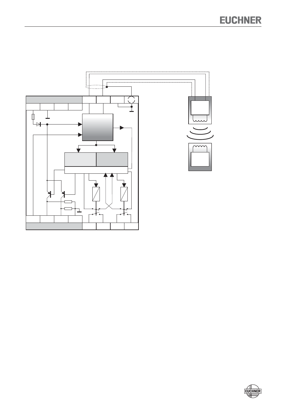
Block diagram
24V
TST
TST
input not connected:
Operation without external testing
0V
OUT
ERR
GND
H11
10k7
10k7
H12
14
13
23
24
SH1
DDSP
CPU-A
CPU-B
KA
KB
white
brown
Screen connection
DDSP:
Double Dynamic
Safety Part with fault
monitoring of the actuator,
read head and the
cable to the read head
CES evaluation unit
Read head
Coded
actuator
Trans-
ponder
Illustration: Actuator not in the operating distance
TST
Test input (see „Self-test with test input TST“ page 16)
OUT
Door monitoring output (not a safety output)
ERR Diagnostic
output
GND
0 V (internally connected with 0 V of the operating voltage)
H11/H12
Read head connection
SH1
Read head shield connection
13/14
Relay contact A connection, safety relay enable
23/24
Relay contact B connection, safety relay enable