Operating instructions safety switches tz...as – EUCHNER TZxxxAS1 User Manual
Page 5
Operating Instructions Safety Switches TZ...AS
1
Correct use
EUCHNER safety switches series TZ...AS are operated
as a slave on the safety bus
AS-Interface Safety at
Work and function as electromagnetic interlocking
devices with guard locking.
In combination with a separating safety guard and
the machine control, this safety component prevents
the safety guard from being opened while a dangerous
machine movement is being performed.
For the control system, this means that
f
starting commands which cause hazardous
situations must become active only when the safety
guard is in protective position and the guard locking
is in locked position.
The locked position of the guard locking must be
released only when the hazardous situation is no
longer present.
Before safety switches are used, a risk assessment
must be performed on the machine, e.g., in accordance
with
f
EN ISO 13849, Safety of machinery - Safety-related
parts of control systems
f
EN 12100-1, Safety of machinery - General
principles for design - Risk assessment and risk
reduction
f
IEC 62061, Safety of machinery - Functional safety
of safety-related electrical, electronic and
programmable electronic control systems
Correct use includes compliance with the relevant
requirements for installation and operation, particularly
f
EN ISO 13849, Safety of machinery - Safety-related
parts of control systems
f
EN 1088, Safety of machinery. Interlocking devices
associated with guards. Principles for design and
selection
f
EN 60 204-1, Electrical equipment of machines.
Important:
f
The user is responsible for safe integration of the
device in a safe overall system. For this purpose,
the overall system must be validated, e.g. in
accordance with EN ISO 13849-2.
f
If the simplified method according to section 6.3
EN ISO 13849-1:2008 is used for validation, the
Performance Level (PL) may be reduced if several
devices are connected one after the other.
f
If a product data sheet is included with the product,
the information on the data sheet applies in case of
discrepancies with the operating instructions.
Safety precautions
Safety switches fulfill a personal protection
function. Incorrect installation or tampering can
lead to severe injuries to personnel.
Safety components must not be bypassed
(bridging of contacts), turned away, removed or
otherwise rendered ineffective.
On this topic pay attention in particular to the
measures for reducing the possibility of bypassing
according to EN 1088:1995.A2:2008, sec. 5.7.
The switching operation may only be triggered
by actuators specially provided for this purpose
which are permanently connected to the
protective guard.
A complete safety-oriented system generally
consists of several signaling devices, sensors,
evaluation units and concepts for safe shutdown.
The manufacturer of a machine or installation
is responsible for correct and safe overall
function.
All safety instructions and requirements stated
in the Operating Instructions of the AS-Interface
safety monitor used must be observed.
Function
EUCHNER safety switches series TZ...AS feature a
slave connection to the safety bus
AS-Interface Safety
at Work. They permit locking of movable safety
guards.
Position monitoring of the safety guard and monitoring
of interlocking are performed via two separate
switching elements (door monitoring contact SK and
solenoid monitoring contact ÜK).
When the safety guard is closed and the guard
locking is active, each TZ...AS sends over the AS-
Interface bus a switch-specific, unique safety code
sequence with 8x4 bits. This code sequence is
evaluated by an AS-Interface safety monitor. The
positively opening contact SK for door monitoring is
mapped via the AS-Interface input bits D0 and D1.
The solenoid monitoring contact ÜK is represented
by the AS-Interface input bits D2 and D3.
The safety switch must be correspondingly configured
in the AS-Interface safety monitor (refer to the
operating instructions of the AS-Interface safety
monitor used and the status table).
Version TZ1...AS
(guard locking by spring force)
For the purpose of the protection of people
against dangerous over-traveling movements, it
is also necessary to switch the black AS-Inter-
face cable (auxiliary power), which is connected
to the AS-Interface distribution box and the
switch, via a standstill monitor or via the safe
switch-on delay feature in a dual-channel AS-In-
terface safety monitor (e.g. door locking for
duration of the delay time).
The guard locking pin is held in the locked position by
spring force and unlocked by electromagnetic actuation.
The spring interlock guard locking functions in accordance
with the closed-circuit current principle. The safety guard
cannot be opened immediately in the event of interruption
of the solenoid power supply.
For the purpose of process protection, the guard
locking solenoid can be switched via the software by
means of AS-Interface output bit D0.
Version TZ2...AS
(guard locking by solenoid force)
This type must be used only in special cases
after strict assessment of the accident risk!
The safety guard can be opened immediately in
the event of interruption of the solenoid power
supply!
The guard locking pin is held in the locked position by
electromagnetic force and released by spring force.
The guard locking operates in accordance with the
open-circuit current principle.
For the purpose of process protection, the guard
locking solenoid can be switched via the software by
means of AS-Interface output bit D0.
f
Closing safety guard and activating guard locking
The guard locking pin is released by insertion of the
actuator into the safety switch.
TZ1...AS: The guard locking pin is moved to locked
position by spring force.
TZ2...AS: The guard locking pin is moved to locked
position when the solenoid operating voltage is
applied.
The safety contacts are closed.
The complete safety code sequence (8 x 4 bits) is
sent via AS-Interface input bits D0 to D3.
f
Deactivating guard locking, opening safety guard
TZ1...AS: The guard locking is deactivated when the
solenoid operating voltage is applied, and release is
issued by means of AS-Interface output bit D0. Sole-
noid monitoring contact ÜK is opened. The value pair
0, 0 is sent during each bus cycle via AS-Interface
input bits D2 and D3.
The actuator can be removed.
Door monitoring contact SK is positively opened and
guard locking is blocked in this position when the actuator
is removed (protection against unintentional closing).
The values 0, 0, 0, 0 are continuously sent via AS-Inter-
face input bits D0 to D3.
TZ2...AS: The guard locking is deactivated when the
solenoid operating voltage is applied, and release is
issued by means of AS-Interface output bit D0. Sole-
noid monitoring contact ÜK is opened. The value pair
0, 0 is sent during each bus cycle via AS-Interface
input bits D2 and D3.
The actuator can be removed.
Door monitoring contact SK is positively opened and
guard locking is blocked in this position when the actuator
is removed (protection against unintentional closing).
The values 0, 0, 0, 0 are continuously sent via AS-Inter-
face input bits D0 to D3.
Mechanical release
In the event of malfunctions, the guard locking can
be released with the mechanical release irrespective
of the state of the solenoid (see Figure 3).
f
Remove key from sealing wire.
f
Remove locking screw.
f
Release by turning the key.
f
The safety guard can be opened.
f
Attach mechanical release again in the reverse
order.
The seal must be restored after use by fitting a new
sealing wire.
Mounting
The switch must be protected against contact
with inflammable material or accidental touching.
Safety switches and actuators must not be used
as an end stop.
Mount the safety switch only in assembled
condition!
Assemble the safety switch so that
f
access to the switch is difficult for operating
personnel when the safety guard is open
f
operation of the mechanical release is still possible
f
address programming, inspection and replacement
by authorized personnel is possible.
f
Insert the actuator in the actuating head.
f
Mount the safety switch positively.
f
Permanently connect the actuator to the safety
guard so that it cannot be detached, e.g. using the
enclosed non-removable screws, rivets or welding.
f
Fit an additional stop for the movable part of the
safety guard.
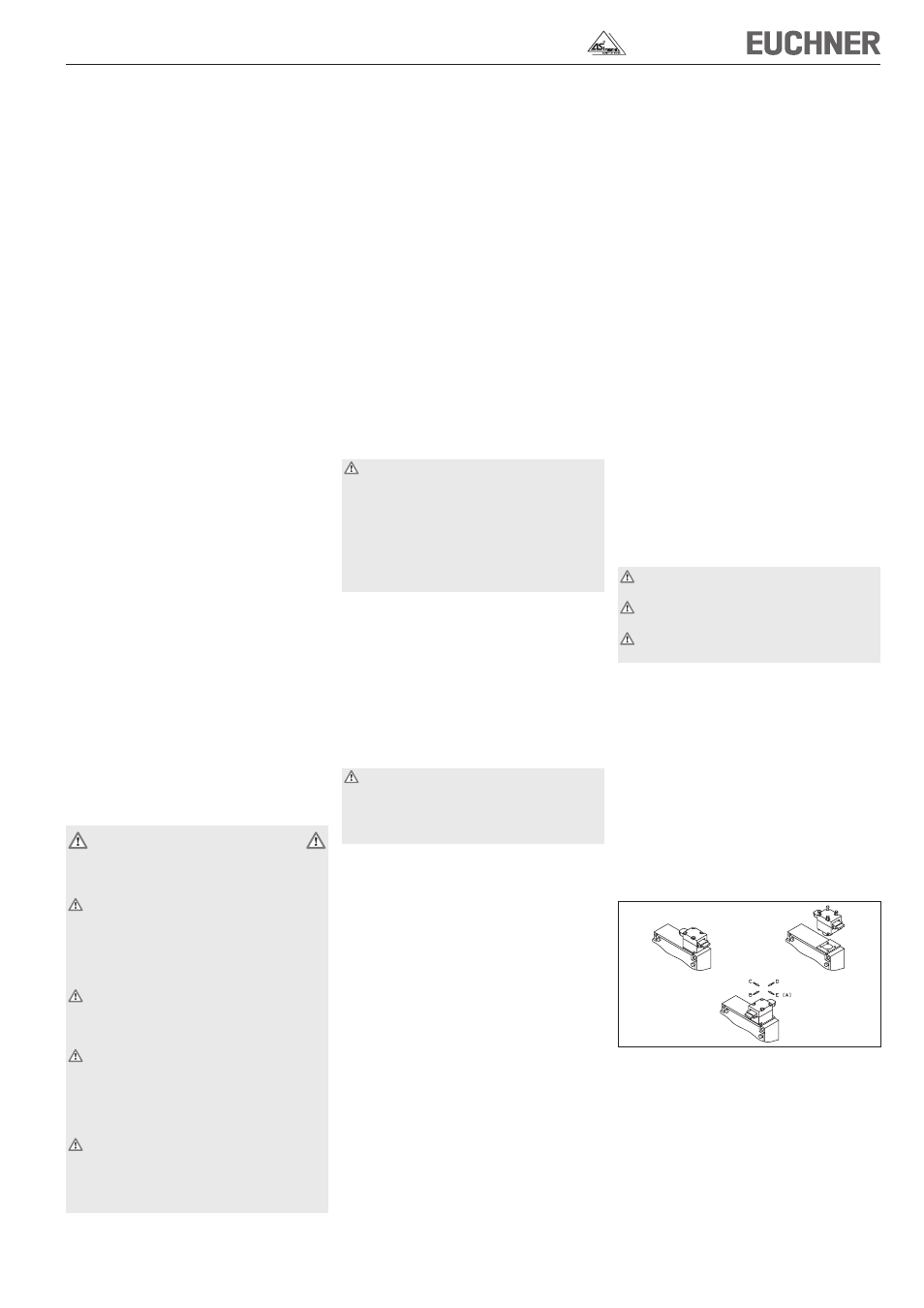
Changing the actuating direction
Figure 1: Changing the actuating direction
f
Insert the actuator in the actuating head.
f
Remove the screws from the actuating head.
f
Set the required direction.
f
Tighten the screws with a torque of 1.2 Nm.
➀
➁
➂