EUCHNER N1A Single hole fixing limit switch User Manual
Page 4
Operating Instructions Precision Single Limit Switches N
1
A
Correct use
Precision single limit switches according to DIN 43
693 are used for positioning and controlling machines
and in industrial installations.
For general applications, snap-action switching
elements ES502E are used. For usage as safety
switches, only the switching elements ES508E,
ES514 and ES588 with positively driven NC contacts
are allowed.
The safety switches are positively driven auxiliary
power switches and comply with the requirements
as per IEC 60947-5-1 / EN 60947-5-1 annex K.
In combination with a separating safety guard
, this safety
device prevents dangerous machine movements from
occurring while the safety guard is open. A stop command
is triggered if the safety guard is opened during the
dangerous machine function.
Before safety switches are used, a risk assessment
must be performed on the machine in accordance
with
EN ISO 13849-1, Safety of machinery. Safety related
parts of control systems. General principles for
design
EN ISO 14121, Safety of machinery. Risk
assessment. Principles.
Correct use includes compliance with the relevant
requirements for installation and operation,
particularly
EN ISO 13849-1, Safety of machinery. Safety related
parts of control systems. General principles for
design
EN 1088, Safety of machinery. Interlocking devices
associated with guards. Principles for design and
selection
EN 60 204-1, Electrical equipment of machines
Incorrect use
Precision single limit switches with switching element
ES502E (snap-action switching contact not positively
driven) must not be used in safety circuits.
Important:
The user is responsible for the integration of the
device in a safe overall system. For this purpose
the overall system must be validated, e.g. in
accordance with EN ISO 13849-2.
If the simplified method according to section 6.3
EN ISO 13849-1:2008 is used for validation, the
Performance Level (PL) may be reduced if several
devices are connected one after the other.
If a product data sheet is included with the product,
the information on the data sheet applies in case of
discrepancies with the operating instructions.
Safety precautions
In safety circuits, only the switching elements
ES508E, ES514 or ES588 with positively driven NC
contacts are allowed.
Precision single limit switches in safety circuits
provide a personal protection function. Incorrect
installation or tampering can lead to severe injuries
to personnel.
Precision single limit switches in safety circuits
must not be bypassed (bridging of contacts),
turned away, removed or otherwise rendered
ineffective.
On this topic pay attention in particular to the
measures for reducing the possibility of bypassing
from EN 1088:1995+A2:2008, section 5.7.
Where precision single limit switches are used
in safety circuits, switches and trip dogs must
be fitted in such a way that they are adequately
secured against movement.
To meet these requirements:
The fixings must be reliable and must also
require the use of a tool to undo them.
The use of slots must be limited to the initial
adjustment.
Precautions must be taken to ensure that there
is no movement after adjustment (e.g. using
bolts or dowel pins).
Mounting, electrical connection and setup only
by authorized personnel.
Function
The switching elements are actuated by means of
plungers. Different plungers and trip dogs are used
depending on the application (operating point
accuracy and approach speed) (see Figure 7).
In general applications the plunger is actuated by trip
dogs in accordance with DIN 69639 which are
mounted with an interference fit in trip rails in
accordance with DIN 69638.
Switching elements / terminal assignment
Fig. 1: Switching elements and terminal assignment
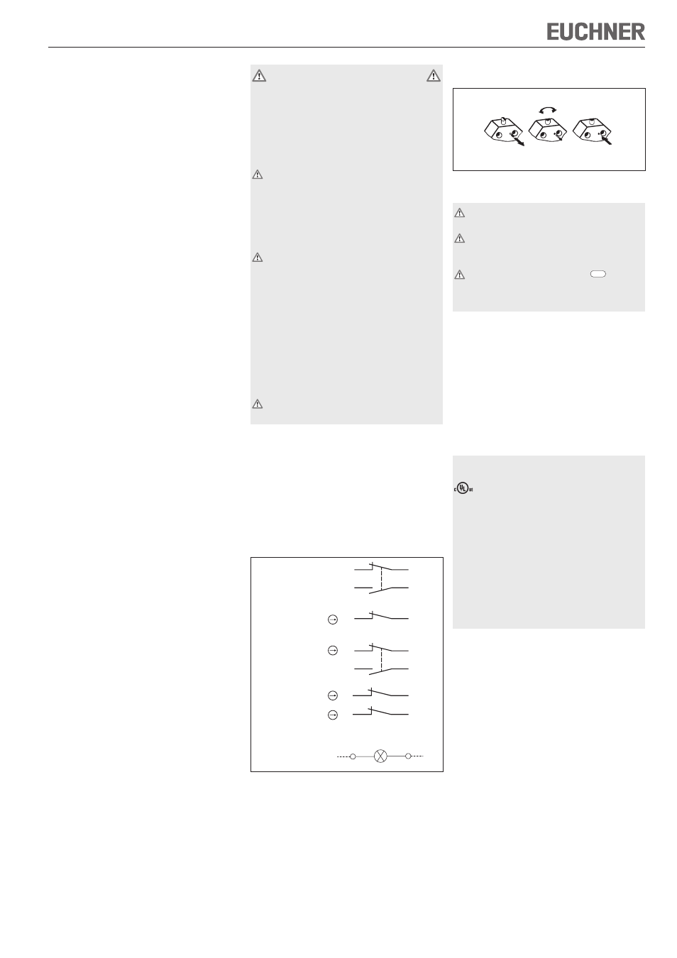
Changing the approach direction
The approach direction can be adjusted by 90° on
chisel and roller plungers.
After unscrewing the locking screw, the plunger can
be changed easily to the required direction.
After changing the direction, the locking screw must
be refitted (see Figure 2).
Figure 2: Changing the approach direction
Mounting
Precision single limit switches must not be used
as an end stop.
When used in safety circuits, positively mount
trip dogs on the machine/safety guard so that
they cannot be detached.
It is imperative that dimension
12
-0,5
(distance
from switch reference surface to trip dog, see
Figure 4) is maintained in safety circuits to ensure
safe contact opening.
Fit precision single limit switches so that
connection cables and plug connectors are not
damaged by moving parts of the machine.
Protection against environmental influences
Safety venting valves are used to equalize the
pressure to protect against the pumping action of
the plunger. They must not be sealed with paint.
Mask plunger, plunger guide, safety venting valves
and rating plate during painting work!
Electrical connection
The following applies for switches with UL approval:
For use and applications as per the requirements of
, a class 2 power supply or a class 2
transformer according to UL1310 or UL1585 must
be used.
Connection cables for precision single limit switches
installed at the place of use must be separated from
all moving and permanently installed cables and un-
insulated active elements of other parts of the system
which operate at a voltage of over 150 V. A constant
clearance of 50.8 mm must be maintained. This does
not apply if the moving cables are equipped with
suitable insulation materials which possess an
identical or higher dielectric strength compared to
the other relevant parts of the system.
When switches with indicators are used, the voltage
range printed on the indicator housing must be
observed (for connection see Figure 1).
Version N1A...M (cable entry)
Open switch cover
Conductor cross-section 0.34 ... 1.5 mm²
For terminal assignment see Figure 1
Fit EUCHNER cable gland M20x1.5 or similar quality
cable gland with captive O-ring. The thread on the
gland must not be longer than 6.5 mm.
Seal cable carefully. Sealing ring must be matched
to the diameter of the cable
Tighten screws for connections to the switching
element to 0.6 Nm (ES588 with 0.3 Nm)
Close switch cover and tighten cover screws to 0.5
Nm.
Version N1A...SVM5 (plug connector M12)
For connector assignment see Figure 8.
ES514
ES508E
ES502E
Shown: switching element not actuated
22
14
21
13
22
21
22
14
21
13
ES2588
(2 x ES588)
2
2
1
1
X1
X2
LED indicator
LE060/LE110/LE220