ElmoMC SimplIQ Digital Servo Drives-Harmonica Installation Guide User Manual
Page 26
Harmonica Installation Guide
Installation
MAN-HARIG (Ver. 1.902)
26
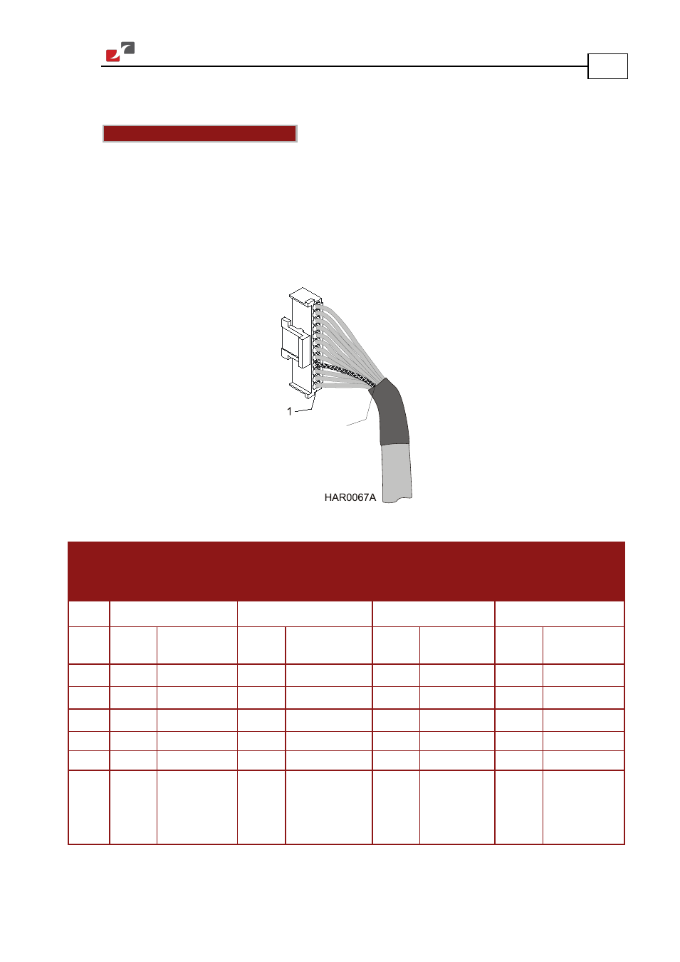
Connect the main feedback cable from the motor to the J3 port on the front of the Harmonica,
using a 12-pin, Molex plug.
Notes for connecting the J3 cable:
•
Use 24 or 26 AWG twisted-pair shielded cables. For best results, the shield should have
aluminum foil covered by copper braid.
•
Connect the drain wire to pin 4.
The drain wire is a non-insulated wire that is in contact with parts of the cable, usually the
shield. It is used to terminate the shield and as a grounding connection.
•
Ground the shield to the motor chassis (except on resolver cables).
Figure 11: The Feedback (J3) Cable
Incremental
Encoder
Interpolated Analog
(Sine/Cosine)
Encoder
Resolver
Tachometer and
Potentiometer
HAR-
XX
/
YYY
_
HAR-
XX
/
YYY
I
HAR-
XX
/
YYY
R
HAR-
XX
/
YYY
T
Pin
(J3)
Signal Function
Signal Function
Signal Function
Signal Function
1
HC
Hall sensor C input HC
Hall sensor C input NC
-
HC
Hall sensor C input
2
HB
Hall sensor B input HB
Hall sensor B input NC
-
HB
Hall sensor B input
3
HA
Hall sensor A input HA
Hall sensor A input NC
-
HA
Hall sensor A input
4
SUPRET
Supply return
SUPRET
Supply return
SUPRET
Supply return
SUPRET
Supply return
5
SUPRET
Supply return
SUPRET
Supply return
SUPRET
Supply return
SUPRET
Supply return
6
+5V
Encoder/Hall
+5 V supply
voltage,
5 V @ 200 mA
maximum
+5V
Encoder/Hall
+5 V supply voltage,
5 V @ 200 mA
maximum
NC
-
+5V
Encoder/Hall
+5 V supply
voltage
Drain Wire