Special note about disconnecting molex connectors, Connecting the auxiliary power cable (j4) – ElmoMC SimplIQ Digital Servo Drives-Harmonica Installation Guide User Manual
Page 24
Harmonica Installation Guide
Installation
MAN-HARIG (Ver. 1.902)
24
3.5.3.
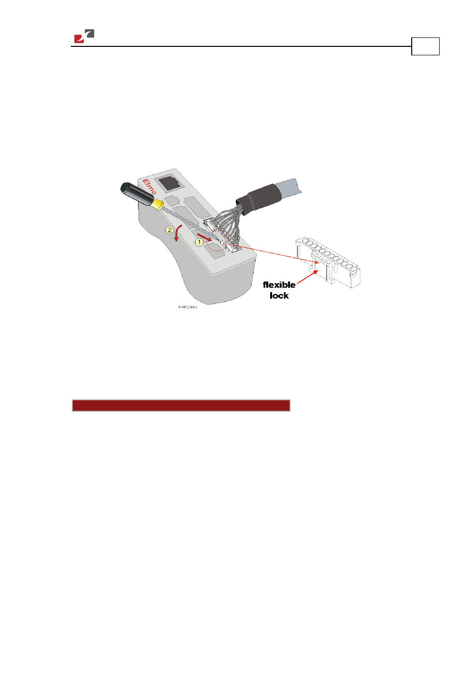
Special Note about Disconnecting Molex Connectors
The Auxiliary Power Cable (J4), the Feedback cables (J2 and J3) and the I/O cables (J5, J6 and J7)
all use 2 mm pitch Molex connectors. These connectors snap together quite easily, but require
a small standard screwdriver for disassembly.
To disassemble the Molex connector:
1.
Slip the screwdriver into the lock: The lock disengages.
2.
Twist the screwdriver downward with light pressure on the handle (see the figure below).
Figure 9: Disconnecting Molex Connectors
3.5.4.
Connecting the Auxiliary Power Cable (J4)
Connect the auxiliary power supply to the J4 port on the front of the Harmonica, using a
2-pin Molex plug. Remember, you are working with DC power; be sure to exercise caution. The
required voltage is 24 VDC.
Notes for 24 VDC auxiliary power supply connections:
•
Use a 24, 26 or 28 AWG twisted pair shielded cable. The shield should have copper braid.
•
The source of the 24 VDC must be isolated.
•
For safety reasons, connect the return (common) of the 24 VDC source to the closest
ground.
•
Connect the cable shield to the closest ground near the 24 VDC source.
•
Before applying power, first verify the polarity of the connection.