Quick attack pkg 1 install guide – Elkhart Brass Sidewinder Quick Attack Pkg 1 Install Guide User Manual
Page 3
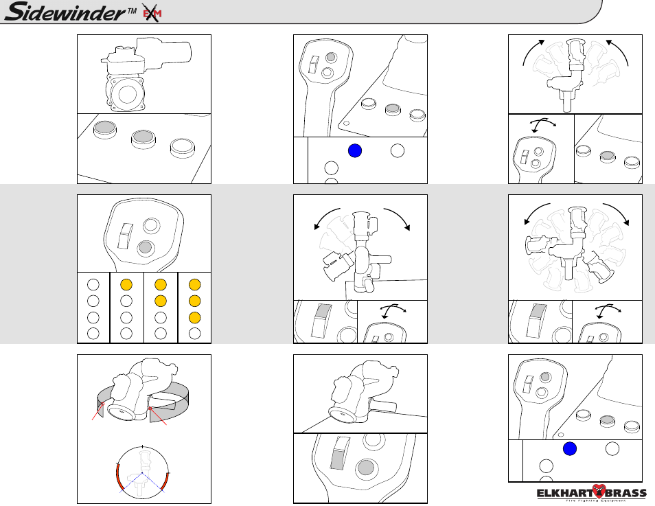
CALIBRATE HORIZONTAL
ENTER SETUP MODE
EXIT SETUP MODE
SET MONITOR SPEED
SET KEEP-OUT ZONES
SET VER TRAVEL LIMIT
SET HOR TRAVEL LIMIT
CALIBRATE VALVE
SET STOW POSITION
3
4
5
2
1
8
7
6
Quick Attack Pkg 1 Install Guide:
3
Setup Mode
Press and hold
and
blue status LED
on monitor box
turns on.
NOTE: Changes
made will not
take effect until
after
exiting
setup mode.
Press and hold
and
blue status LED
on monitor box
turns off.
The
following
steps
are
optional (O).
Pressing
the
cycle through the
monitor
motor
speed options:
LEDs - Ver / Hor
0 - Fast / Fast
1 - Slow / Fast
2 - Fast / Slow
3 - Slow / Slow
Move monitor to
desired position,
then press
and
same time to
store a stow
position.
Stow
position
must be within
allowed limits of
travel.
Move monitor to
a travel limit
position.
Hold
move the joystick
forward to set the
lower limit, and
pull back to set
the upper limit.
MAX travel of
135° below the
pre-calibrated
“zero” position.
This step is
required (R).
Aim monitor at
center
forward
“zero” position.
Hold
then move the
joystick to the
and hold until
status LED on
monitor blinks &
returns to solid.
NOTE: You will
also need to
calibrate
the
valve before use.
While you are
NOT in setup
mode, press and
hold
and
approximately 5
seconds.
The
valve
will
a u t o m a t i c a l l y
start to calibrate
itself.
98326010 Rev. A
(R)
(O)
(O)
Lower Left:
Move to top/right
corner of the
lower left zone,
hold
press
and release both.
Lower Right:
Move to top/left
corner of the
lower right zone,
hold
press,
and release both.
(O)
(O)
Move monitor to
a travel limit
position.
Hold
move the joystick
left to set the left
limit, and to the
right to set the
right limit.
MAX travel of
175° in either
direction from the
calibrated “zero”
position.
(O)
U
L
STATUS
POWER
Preset
Preset
Stream
Preset
STATUS
POWER
Lower Left Zone:
Top right corner
Lower Right Zone:
Top left corner
0°
Right Travel Limit
Left Travel Limit
Lower Left
Zone
Lower Right
Zone
Close
Preset
Right
Left
Up
Down
R
L
Stream
Right
Left