Quick attack pkg 1 install guide, Control components & accessories – Elkhart Brass Sidewinder Quick Attack Pkg 1 Install Guide User Manual
Page 2
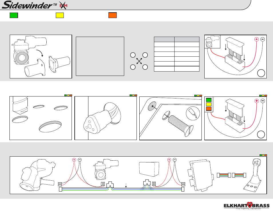
Quick Attack Pkg 1 Install Guide:
Control Components & Accessories
2
4.
5.
6.
A. Follow mounting templates on page
30 of the instruction manual for hole
diameters and dimensions.
B. Drill holes for CAN network and
power cables for each components’
leads behind each component.
C. Mount components to panel using
10-24 x 1/2” screws. Use Loctite 242 or
equivalent.
D. Add a 1A (12VDC)* fuse between
red component lead and positive power
lead.
A. Connect entire CAN network together using 18-22 AWG. Ensure every component connected to the CAN network is connected in between 2 end components that
have CAN termination. Please refer to the BLUE, GREEN, and BLACK lines as the CAN wires below.
*.5A (24VDC)
- Joystick Controller
- OEM Interface Module
- Position Feedback Display
A. Install valve into plumbing. Torque
adapter bolts to spec using
Figure 1.
7/32” dia.
unless noted
CAN
Network
Wires
18g
98326010 Rev. A
NOTE: If you need to change
the orientation of the electric
actuator on top of the valve,
follow the instructions on
page 16 of the Unibody Valve
Manual (98311000). Manual
can be found at:
www.elkhartbrass.com/down
loads/manuals
Figure 1: Torque Specs
Valve
Torque
EB15
25-30 ft-lbs
EB20
25-30 ft-lbs
EB25
25-30 ft-lbs
EB30
38-40 ft-lbs
EB35
38-40 ft-lbs
EB40
60-70 ft-lbs
1
3
4
2
Tighten Adapter
Bolts using a
cross pattern
B. Add a 30A(12VDC)* fuse between
RED controller lead and positive power
lead. *15A(24VDC)
16g
oo
oo
o
o
o
o
o
o
o
oo
oo
ooooo
oo
o
o
o
o
o
o
o
oo
ooo
oooo
oo
o
o
o
o
o
o
o
oo