Doug Fleenor Design ColorWheel User Manual
Page 2
Page 2 of 5
distances involved. Typically, two #16 AWG wires are used for this purpose. The low
voltage power cabling can be run in the same conduit with the DMX512 data cable.
DMX512 data connection
The Color Wheel produces standard DMX512 data. The DMX512 cable should be
connected to the ‘C’, ‘-‘, and ‘+’ terminals as shown in the table below.
Terminal Label
Function
Wire
‘C’
Common
Shield
‘-‘
DMX data minus
typically white/blue
‘+’
DMX data plus
typically blue/white
For reliable operation, a suitable DMX512 cable must be used. Examples include
Belden 9829, Belden 9729, and Alpha 9817.
DMX512 cabling must be wired in a daisy chain fashion. The last device on the line
must be fitted with a terminating resistor. If you are not familiar with DMX512 wiring
practices, we suggest that you consult with your dealer.
Installation
The Color Wheel can be installed in any standard single gang wall box with a depth of at
least 1.5 inches. Examples of acceptable wall boxes include Raco models 420, 611,
650, 660, and 674.
After making the electrical connections, screw the Color Wheel to the wall box using the
supplied screws.
Power Up and Configuration
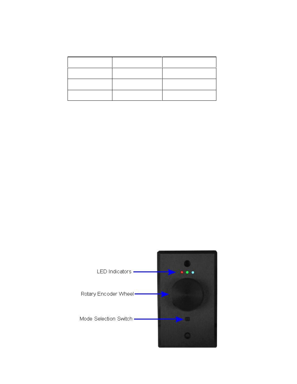
The Color Wheel has three LED indicators, a rotary encoder with a push button feature,
and a square mode selection switch. The left LED is red. The center LED is a tri-color
device (red, green, blue), and the right LED is blue. This allows the Color Wheel to
display many color and control combinations.