Det-Tronics PW9200x Pathwatch IR Gas Detection System User Manual
Page 9
SITE REQUIREMENTS
If the instrument is located where it is exposed to
direct sunlight, a sunshield should be installed to
keep the instrument housing temperature within the
specified operating limit.
If the instrument is installed in a high temperature,
high humidity or corrosive atmosphere, instrument air
or dry nitrogen purge is recommended.
Do not install the instrument so that the receiver
directly faces an intense heat source.
CAUTION
If power is to be disconnected for an extended
period, (e.g., over one week) the instrument
should be removed to a protected environment.
MOUNTING
The PW9200 is installed so that the transmitter and
receiver face each other. If a mirror is used with the
PW9200, see APPENDIX for special mount assembly
and alignment procedures.
The transmitter and receiver are bolted to the pan-tilt
mount, illustrated in Figures 4 and 5. This mount per-
mits height, horizontal pan and vertical tilt adjust-
ments to optically align the instrument for maximum
signal strength. The pan-tilt mount attaches to a user
supplied 4 inch I.D. (4.5 inch O.D.) vertical pipe,
which must be securely stabilized to assure retention
of alignment over time and temperature fluctuations.
The vertical pipe should also be isolated against
external vibration.
1.
Loosen the bolt holding the alignment target to
the back of the front plate and rotate the target
180°. Add the two other 1/4-20 x 3/4 inch screws,
nuts and lockwashers provided and secure the
target.
2.
Slide the alignment scope (packed between the
plates of the mount) marked “R” onto the grooved
bracket of the mount marked “R”. Roughly center
the alignment scope on the bracket and firmly
tighten the scope mount clamp screws. Repeat
for the scope and mount marked “T”. Be sure to
match the serial number of the scope to the serial
number of the mount.
NOTE
Do not discard the protective end caps for the
scopes. They should be replaced when optical
alignment has been completed.
7
95-8400
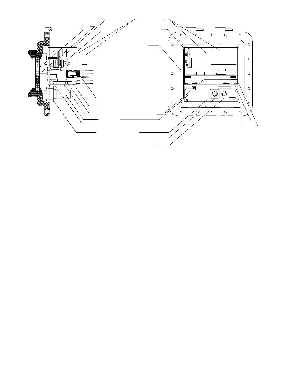
DC POWER SUPPLIES
OPTICAL FILTER
THERMOELECTRICALLY
COOLED PHOTODETECTOR
FILTERWHEEL MOTOR
STATUS RELAY
REAR PANEL PC BOARD
CONNECTOR/RELAY PC BOARD
OPTIONS PC BOARD
SIGNAL CONNECTOR
POWER CONNECTOR
IR LENS
IR WINDOW
FILTERWHEEL
REAR PANEL PC BOARD
PREAMP GAIN CONTROL
AGC/TE COOLER PC BOARD
PREAMPLIFIER
PC BOARD
SYNC PICKOFF
A1396
DUAL RATIO PC BOARD
Figure 3—Location of Receiver Boards and Assemblies