Det-Tronics PW9200x Pathwatch IR Gas Detection System User Manual
Page 5
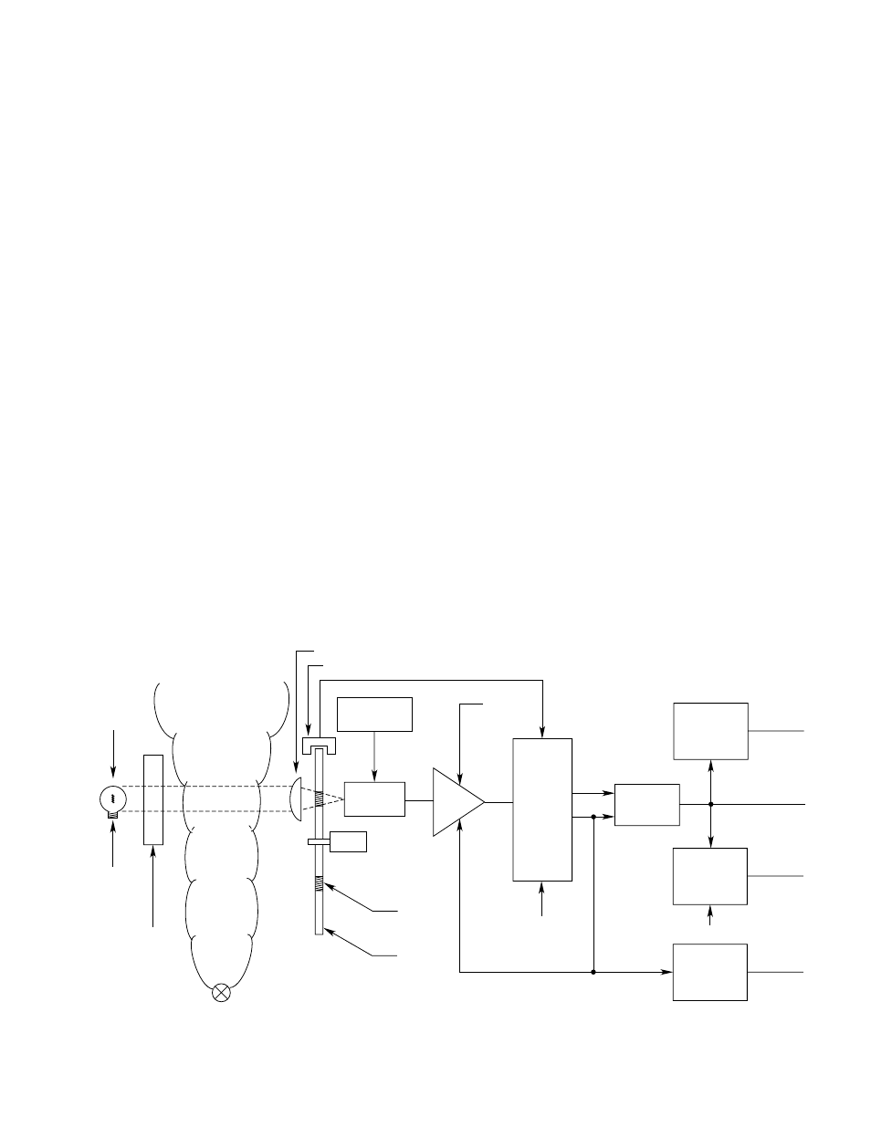
Filterwheel Motor
This motor is a small 115 vac shaded pole ball bear-
ing motor. The filterwheel is attached to the motor
shaft.
Filterwheel
The filterwheel is located between the receiver lens
and the photodetector. It contains the DENOMINA-
TOR (active) and NUMERATOR (reference) optical
interference filters. Rotating at a rapid rate, the filter-
wheel chops the incoming light beam and alternately
passes infrared light at the two distinct wavelengths
to the photodetector.
Sync Pickoff
The sync pickoff is a small U-shaped optical switch,
which is mounted on the rear panel printed circuit
board and straddles the filterwheel. It senses when
each filter is in front of the infrared photodetector and
generates the synchronization signal.
Photodetector
The infrared photodetector is mounted at the focal
point of the receiver lens. The photodetector converts
the intensity of the incoming infrared light to a propor-
tional electrical signal. It alternately senses the light
intensity at both wavelengths during each revolution
of the filterwheel. The photodetector is thermo-electri-
cally cooled to increase the sensitivity to infrared light.
Amplifiers
The signal at the photodetector is amplified by the
preamplifier circuitry. The gain of the preamplifier
can be adjusted with a potentiometer to optimize the
signal strength for long or short operating distances.
The amplified signal is fed to the AGC amplifier,
which maintains the signal within the proper operating
range.
Signal Processing Electronics
The signal from the AGC Amplifier is separated into
two outputs: active (DENOMINATOR) and reference
(NUMERATOR).
Ratiometer
The ratiometer circuit generates an analog output by
calculating the ratio of the NUMERATOR (reference)
signal to the DENOMINATOR (active) signal.
Optional 4 To 20 Milliampere Converter
This option converts the 0 to 10 vdc voltage (RATIO
output) into a 4 to 20 ma current. A load resistor is
connected between the RATIO output and the analog
ground and can be any value between 0 and 500
ohms.
3
95-8400
Figure 1—Functional Block Diagram
SIGNAL
PROCESSING
ELECTRONICS
RATIOMETER
OPTIONAL
4 TO 20 MA
CONVERTER
THRESHOLD
DETECTOR
THRESHOLD
DETECTOR
STATUS
ALARM
RELAY
ALARM
RELAY
OPTIONAL
ANALOG
OUTPUT
ANALOG
OUTPUT
AMPLIFIER
MOTOR
INFRARED
PHOTO
DETECTOR
THERMOELECTRIC
COOLER
CONTROL
TRANS-
MITTER
LAMP
VAPOR CLOUD
BEING DETECTED
RECEIVER OPTICS
SYNC PICKOFF
MANUAL
GAIN
CONTROL
DENOM.
NUM.
MODE
SELECT
RATIO
OPTICAL
FILTERS
FILTER
WHEEL
TRANSMITTER
OPTICS
REGULATED
DC
POWER
SUPPLY
ADJUST
A1393