Specifications – Det-Tronics U7698A, B, C, E Unitized Frequency IR Detector/Controller User Manual
Page 5
Two LEDs are located inside the detector viewing win-
dow and are illuminated whenever the fire relay is ener-
gized.
oi FEATURE
The U7698B is equipped with the Optical Integrity (
oi)
feature (manually initiated). This patented system
assures proper operation of the detector by checking
the cleanliness of the optical surfaces, sensitivity of the
IR sensor, and proper functioning of the electronic cir-
cuitry. The
oi test is accomplished without the use of an
external IR source. It can be performed at any time by
the operator in the control room by simply pressing a
button. (Fire response equipment must be disabled dur-
ing the
oi test to prevent actuation.) The normally open
switch used to activate the manual
oi test must be con-
nected between the “
oi” terminal and the “–” of the
power supply. The “
oi” terminal must be at less than 0.1
volt to activate the
oi test.
The
oi system generates a low level flickering IR test
beam using two small IR test lamps that are located
inside the detector enclosure. An optical shield prevents
this test beam from reaching the sensor directly.
Instead, the test beam travels through the viewing win-
dow where it strikes a reflective
oi ring and is directed
back through the window and into the sensor. See
Figure 3. The sensor then generates an electrical signal
that is processed by the circuitry in the controller. A suc-
cessful
oi test results in activation of the alarm relay and
illumination of the red LEDs inside the detector viewing
window. If the detector optics are dirty or an IR module
problem has caused a decrease in sensitivity to the
point where approximately 50% of the detection range is
lost, the detector will fail the
oi test. Since the oi test
beam must pass through the same portion of the viewing
window as IR radiation generated by a fire, the
oi sys-
tem provides a reliable test of the ability of the detector
to “see” a fire. The fault relay is unaffected by the
oi
test.
DETECTOR ENCLOSURE
The U7698B features an explosion-proof housing that is
designed for installation in hazardous locations in both
indoor and outdoor environments. The detector is not
affected by adverse weather conditions such as wind,
rain, snow, high humidity, or extremes of temperature or
pressure.
SPECIFICATIONS
OPERATING VOLTAGE—
24 vdc nominal, 18 to 32 vdc maximum.
POWER CONSUMPTION—
1.0 watt nominal, 3.5 watts maximum during
oi test.
POWER ON DELAY—
8 seconds. The fault relay will energize in less than 1
second.
OUTPUT RELAYS—
The U7698B has two Form C (N.O. and N.C.) relays.
The normally de-energized alarm relay is programmable
for either latching or non-latching operation. The nor-
mally energized fault relay is de-energized in the event
of a power failure or removal of the IR module.
RESET TIME—
Reset requires 0 volts at the detector for 2.0 seconds
(when latching operation is selected).
RELAY CONTACT RATING—
Form C, rated 2 amperes at 30 vdc.
SPECTRAL SENSITIVITY RANGE—
4.2 to 4.7 microns.
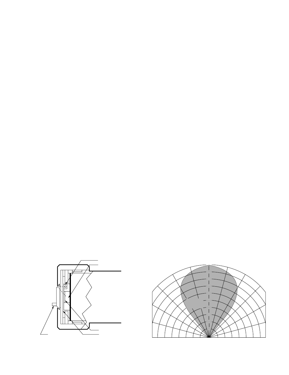
CONE OF VISION—
80 degree cone of vision. See Figure 4 .
IR DETECTOR
IR TEST LAMP (2)
IR SENSING ELEMENT
SNAP-IN
oi
RING
OPTICAL FILTER
VIEWING WINDOW
A1291
Figure 3—Optical Integrity Feature
3
95-8353
0
°
15
°
30
°
45
°
15
°
30
°
45
°
A1461
100
90
80
70
60
50
40
30
20
10
DETECTION
DISTANCE
(PERCENT)
100% REPRESENTS THE MAXIMUM DETECTION DISTANCE FOR A
GIVEN FIRE. THE SENSITIVITY INCREASES AS THE ANGLE OF
INCIDENCE DECREASES.
Figure 4—Cone of Vision