Startup procedure – Det-Tronics U7698A, B, C, E Unitized Frequency IR Detector/Controller User Manual
Page 10
5.
Route the field wiring through the detector conduit
entry.
6.
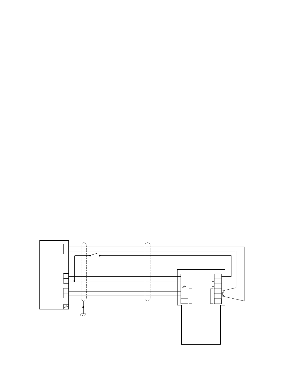
Attach the wires to the appropriate screw terminals
on the terminal block. Refer to Figure 8 for wiring a
single unit and Figure 9 for a multiple configuration.
Connect the shield to earth ground at the power
source. Do not ground the shield at the
detector/controller housing (unless required by local
codes).
7.
To wire the
oi test switches, connect a normally
open switch between the negative (–) side of the dc
power source and the terminal marked “
oi” on the
detector terminal block. Each detector must have
its own
oi test switch.
8.
Check all field wiring to be sure that the proper con-
nections have been made. If conduit is used, pour
the conduit seals and allow them to dry.
9.
Remove the IR module from its shipping package.
10. The alarm relay is factory programmed for latching
operation. To program the relay for non-latching
operation, a jumper plug that is located on the IR
module must be re-positioned. See Figure 6 to
locate the jumper plug. Refer to the label on the
side of the IR module to determine the correct posi-
tion for the jumper plug.
11. Thread the wire leads and keyed connector plug
through the slotted opening on the IR module. Plug
the IR module into the two banana plugs in the bulk-
head.
NOTE
The two oi lamps should be at the top of the detec-
tor (when viewed from the front) and the opening
on the oi ring should be directly opposite the test
lamps. This will ensure proper operation of the oi
system and also minimize the accumulation of
moisture and contaminants between the oi ring
and the viewing window.
12. Connect the keyed connector plug to the 4-pin con-
nector on the IR module.
13. Replace the terminal housing and the sensor hous-
ing. The O-rings must be properly seated to ensure
the water-tight and explosion proof integrity of the
housing. If the unit is equipped with cover locking
clamps, loosen the clamps sufficiently so that the
clamp catches can be seated in the blind holes on
the bulkhead. Fasten the clamps securely using a
5/32 inch hexagonal (Allen) wrench. (See Figure 7.)
14. For best
oi performance, the opening on the oi ring
should be positioned directly opposite the two
oi
test lamps. In addition, the opening should be
pointed down to minimize the accumulation of mois-
ture or contaminants behind the ring.
STARTUP PROCEDURE
When the installation of the equipment is complete, the
following startup procedure should be performed.
1.
Disable any extinguishing equipment that is con-
nected to the system.
2.
Apply input power to the system. Allow an 8 second
power-on delay.
FIRE ALARM PANEL
ALARM
INPUT
EOL DEVICE
**
CENELEC RESISTOR VALUES:
END OF LINE: 5 WATT WITH 2 WATT MINIMUM DISSIPATION
FIRE: 2 WATT WITH 0.7 WATT MAXIMUM DISSIPATION
NO
COM
NC
**
oi
TEST
+
–
+
–
A1293
oi
NO
COM
NC
SPARE
SPARE
F
I
R
E
F
A
U
L
T
U7698B
24 VDC
FAULT
FAULT RELAY SHOWN DE-ENERGIZED
*
*
Figure 8—Typical Wiring Diagram
8