Theory of operation, Installation – Det-Tronics U7099 Dual Frequency IR Detector/Controller User Manual
Page 4
THEORY OF OPERATION
DETECTION
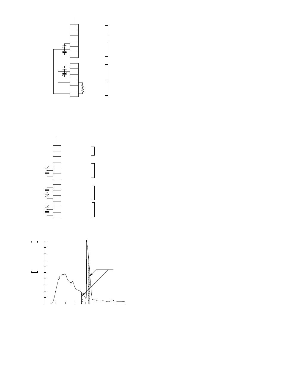
The detector of the U7099 consists of two thermopile
sensors. These devices are sensitive to a broad band of
infrared radiation, but are equipped with sapphire opti-
cal filters that only permit certain wavelengths of radia-
tion to reach the sensor. One sensor is sensitive to IR
radiation at 4.03 microns and the other at 4.45 microns.
SIGNAL PROCESSING
Figure 7 is a block diagram that illustrates the major
components of the signal processing circuitry. The IR
radiation to each sensor channel is transmitted through
bandpass filters, and the output signal from each sen-
sor channel is amplified. The gain control is automati-
cally varied, depending on the input level. This gain
control operates on both channels simultaneously to
preserve and provide accurate signal information for
ratio comparison. The signals are then checked to
ensure that both channels are operating synchronously
to prevent a single sensor from activating the system.
Signals from the synchronous detector are introduced to
the ratio comparator, which compares the level of the
two sensor signals. The threshold detector compares
the intensity of the sensor 1 channel signal to a preset
reference. The startup delay inhibits the alarm output(s)
after initial power-up, allowing approximately 60 sec-
onds for the sensors to stabilize.
If the startup delay is over, the ratio of the two sensor
signals is a fire signal. If the intensity of the sensor 1
signal exceeds the threshold level and the two signals
are synchronous, the “and” gate activates an alarm sig-
nal that causes the Fire and (if applicable) Auxiliary Fire
relays to energize. These relays remain energized until
5 to 15 seconds after the fire is no longer detected. If
one or more of the four criteria is not met, the alarm sig-
nal is inhibited and the Fire relays remain de-energized.
The startup delay also inhibits the fault output for approxi-
mately 60 seconds after initial power-up, allowing the
sensors to stabilize and the Fault relay to energize. In the
event of a power failure or when power is removed, the
Fault relay will de-energize, indicating a fault condition.
INSTALLATION
The U7099 has a nominal 90 degree cone of vision.
Consider an installation having a height of 20 feet (6
meters) and assume it is desired to have complete
detector coverage at a level 10 feet (3 meters) above
ground. If a detector is mounted at the top and pointed
3
95-8272
1
2
3
4
5
6
7
8
9
B
A
NEGATIVE
POSITIVE
NOT USED
NORMALLY CLOSED
COMMON
NORMALLY OPEN
NORMALLY OPEN
COMMON
NORMALLY CLOSED
+
18 TO
+
32 VDC
INPUT VOLTAGE
FIRE RELAY
CONTACTS
FAULT RELAY
CONTACTS
END OF LINE
*
RESISTOR CONNECTIONS
B0915
FIRE RELAY
(SHOWN IN
NO FIRE CONDIITON)
FAULT RELAY
(SHOWN IN
NO FAULT CONDIITON)
INTERNAL WIRING
EXTERNAL WIRING
8.25 KILOHM END OF LINE RESISTOR IS INSTALLED FOR USE IF REQUIRED. IF NOT REQUIRED,
REMOVE THE END OF LINE RESISTOR FROM THE TERMINAL BLOCK (SEE FIGURE 9).
WITH THE END OF LINE RESISTOR INSTALLED, THERE WILL BE CONTINUITY
BETWEEN FIRE RELAY COMMON (TERMINAL 5) AND FAULT RELAY COMMON (TERMINAL 8).
IF A DIFFERENT VALUE END OF LINE RESISTOR IS REQUIRED, REMOVE THIS RESISTOR
AND REPLACE WITH ONE OF REQUIRED VALUE.
*
8.25K
0.25W
Figure 4—U7099 Wiring Diagram
1
2
3
4
5
6
7
8
9
10
11
12
NEGATIVE
POSITIVE
NOT USED
NORMALLY CLOSED
COMMON
NORMALLY OPEN
NORMALLY OPEN
COMMON
NORMALLY CLOSED
NORMALLY CLOSED
COMMON
NORMALLY OPEN
+
18 TO
+
32 VDC INPUT VOLTAGE
FIRE RELAY CONTACTS
(SHOWN WITH NO FIRE DETECTED)
FAULT RELAY CONTACTS
(SHOWN WITH NO FAULT)
AUXILIARY FIRE RELAY CONTACTS
(SHOWN WITH NO FIRE DETECTED)
A1691
INTERNAL WIRING
EXTERNAL WIRING
Figure 5—U7099 Wiring Diagram with Optional Auxiliary Fire Relay
DUAL FREQUENCY
INFRARED SENSOR
RESPONSE
SPECTRA RADIANT
INTENSITY
WATTS
MICRON X STERADIAN
0
1
2
0
8
4.03
SENSOR 1
4.45
SENSOR 2
WAVELENGTH (MICRONS)
A1374
Figure 6—Emission Spectrum of Hydrocarbon Fires at Sea Level