System description – Det-Tronics U7099 Dual Frequency IR Detector/Controller User Manual
Page 3
RELAY OPERATION—
Fire (standard) and Auxiliary Fire (optional) Relays: These
two relays are de-energized with no fire present, as shown
in Figures 4 and 5. They energize when a fire is present
that meets all criteria, and remain energized until 5 to 15
seconds after the fire is no longer detected. Fire relay is
standard, additional Auxiliary Fire relay is available.
Fault Relay: This relay is energized with no fault present,
as shown in Figures 4 and 5. The Fault relay energizes
after an initial startup delay of 45 to 60 seconds when
power is first applied. In the event of a power failure or
when power is removed, the Fault relay will de-energize.
SYSTEM DESCRIPTION
The U7099 Unitized IR Detector/Controller is a dual fre-
quency device that contains all electronic, sensing and
switching components in the same explosion-proof
enclosure. The device requires no external controller
and provides one Fire relay output (NO/NC contacts)
and one Fault relay output (NO/NC contacts). An
optional model that includes the standard Fire and Fault
relays (as described above) plus an additional Auxiliary
Fire relay (NO/NC contacts) is also available. The Fault
relay is normally energized with power applied and no
faults present and deactivates in the event of an internal
malfunction or power failure.
The Det-Tronics U7099 Unitized Dual Frequency
Infrared (IR) Detector/Controller features two sensors,
each looking at different wavelengths in the infrared
spectrum. The signals from the sensors are used to
detect particular spectral characteristics of burning
hydrocarbon fires, and are processed so that false
alarms from “blackbody sources” are reduced. Since
electric arcs do not emit significant radiation at the
response frequencies of the U7099, false actuations
from arc welding will not occur. Its performance is rela-
tively unaffected by smoke, and contamination of optical
surfaces by such things as oil and grease have only
moderate effect. Figure 6 illustrates the typical emission
spectrum of hydrocarbon fires at sea level. The
response range of the two sensors used in the U7099 is
represented by the cross-hatched areas. Note that the
fire emission intensity at the sensor 2 channel is greater
than that at the sensor 1 channel. Before producing a
fire indication, the U7099 IR Detector/Controller per-
forms the following verification processes:
1. Measurement of signals from the two sensor channels.
2. Determination of the signal ratio between the two
channels.
3. Detection of a signal on the 4.03 micron channel
that is greater than a predetermined reference level.
4. Determination that the 4.45 and 4.03 micron radia-
tion is synchronous.
Potential false alarm sources such as welding arcs and
lightning will not satisfy the above requirements, and are
therefore ignored by the Detector/Controller.
2
DETECTOR
DISTANCE
(FEET)
1000
100
10
1
1
10
100
1000
GASOLINE PAN FIRE DIAMETER (INCHES)
A0579
Figure 1—Response of the Detector to Fire at Varying Distances
0
°
15
°
30
°
45
°
15
°
30
°
45
°
A1684
100
90
80
70
60
50
40
30
20
10
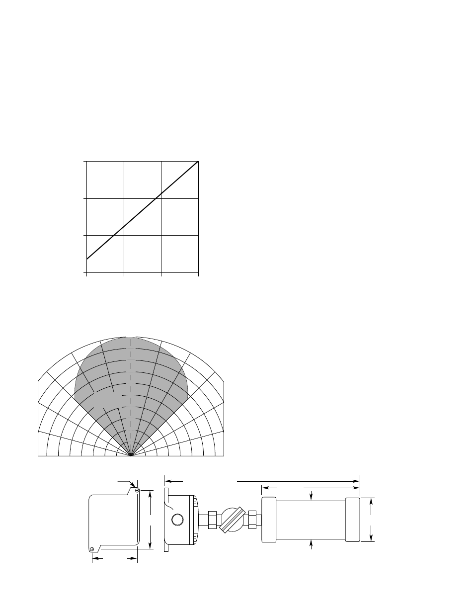
DETECTION
DISTANCE
(PERCENT)
100% REPRESENTS THE MAXIMUM DETECTION DISTANCE FOR A
GIVEN FIRE. THE SENSITIVITY INCREASES AS THE ANGLE OF
INCIDENCE DECREASES.
Figure 2—U7099 Cone of Vision
3.75
(95.25)
4.25
(107.95)
9.38 (238.25)
18.75 (REFERENCE) (476)
5.25
(133.4)
4.12 (104.8)
5/16 (8)
A0895
Figure 3—Dimensions in Inches (MM)