Det-Tronics X3302 Multispectrum IR Flame Detector with Pulse Output User Manual
Page 9
7
95-8578
6.1
Detector Wiring
Important
If installing an X3302 in place of an existing
detector, be sure to move the “A” lead (detector
power) at the controller from the +290 Vdc source
to the +24 Vdc source. Do not apply 290 Vdc to
the X3302.
1. Make field connections following local ordinances
and guidelines in this manual.
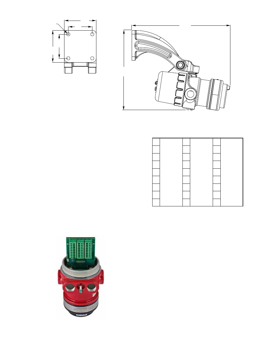
Figure 4 shows the wiring terminal strip located
inside the detector’s integral junction box.
Figure 5 shows the wiring terminal identification for
the X3302 Flame Detector with pulse output.
Leave the shield open at the detector end and
permanently isolate it from accidental contact with
the case and/or other conductors. At the controller/
fire panel end, connect the shield and power minus
(–) to chassis (earth) ground either directly or
through a 0.47 µF 400 Volt non-polarized capacitor
(not supplied). (Refer to Figures 6 through 10.)
Figures 11 and 12 provide examples of typical
installations with a X3302 wired to a fire alarm
panel.
Figure 13 shows an EOL resistor installed within the
integral wiring compartment of the detector (refer to
“EOL Resistors” for details).
2. Check all field wiring to be sure that the proper
connections have been made.
9
8
7
6
5
4
3
2
1
19
18
17
16
15
14
13
12
11
PULSE OUT
COM FIRE
COM FIRE
N.O. FIRE
N.O. FIRE
N.C. FIRE
N.C. FIRE
COM FAULT
COM FAULT
N.O. FAULT
N.O. FAULT
24 VDC +
24 VDC +
24 VDC –
24 VDC –
24 VDC –
29
28
27
26
25
24
23
22
21
SPARE
SPARE
RS-485 A
RS-485 B
MAN
Oi
B2070
figure 5—X3302 Pulse Wiring Terminal Identification
figure 4—X3302 Terminal Block
figure 3—Q9033 mounting arm without Collar attachment Dimensions in Inches (cm)
(See figure 1 for Correct Detector Orientation .)
13.1
(33.3)
10.6
(27.0)
4.0
(10.2)
4.0
(10.2)
3.0
(7.6)
3.0
(7.6)
4X ø0.42
(1.1)
F2069
NOTE: THIS ILLUSTRATION SHOWS THE
DETECTOR MOUNTED AT THE 10° MINIMUM.
THESE DIMENSIONS WILL CHANGE BASED
ON THE DETECTOR’S MOUNTING ANGLE.