Dascom DM-220 User Guide User Manual
Page 36
Tally Dascom DM-210/220
24
Parallel Interface Pin No.25 Below is the pin signal definition of parallel interface socket:
Pin No
Signal Name
Direction
Illumination
1
/STB
Input
Select trigger, input data when the signal is at falling
edge.
2
3
4
5
6
7
8
9
DATA1
DATA2
DATA3
DATA4
DATA5
DATA6
DATA7
DATA8
Input
Input
Input
Input
Input
Input
Input
Input
These signals indicate the parallel data information from
the first to eighth bits. For each signal, when the logic is
“1” indicates “high level”, when the logic is “0” indicates
“low level”.
10
/ACK
Output
For responsion pulse, “low” level indicates that the
printer has accepted the data and be ready for accepting
next data.
11
BUSY
Output
“High” level indicates that the printer is “busy” and can
not accept data now. “Low” level indicates “idle”.
12
PE
Output
Drop down to “Low” level with resistance, “High” level
indicates paper end.
13
SEL
Output
Full up to “High” level with resistance and the “High”
level indicates the printer is online.
15
/ERR
Output
Full up to “High” level with resistance and the “High”
level indicates no error.
14
/AUTOFD
Input
Auto paper feed
16
/INIT
Input
Initialize the printer
17
/SELIN
Input
online
18-25
GND
---
GND,logic “0” level
Note: (1) “Input” indicates
signals from PC to printer
“Output” indicates
signals from Printer to PC
(2) The average logic level of signal is TTL level.
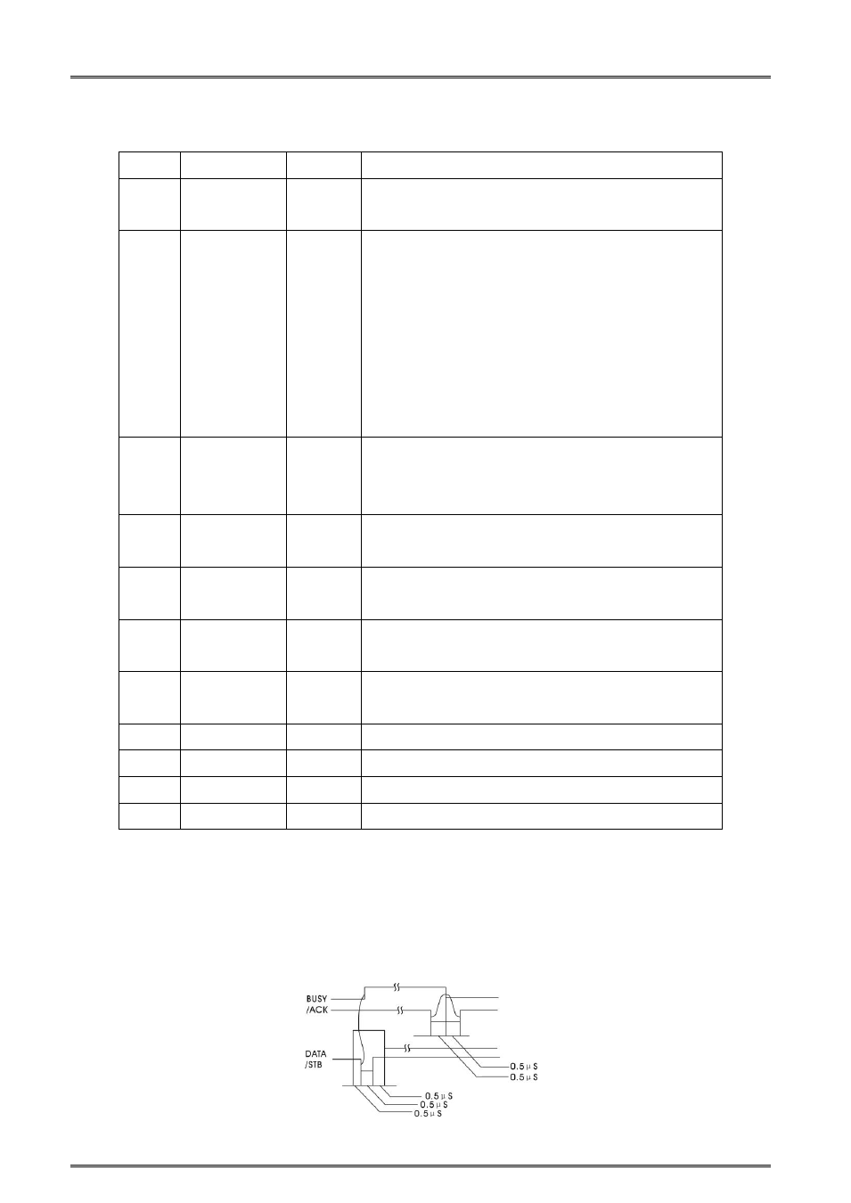
Signal Timing Diagram for parallel interface as shown below: