Clarus environmental variable level pump switch, Figure 8 (b), Figure 10 – Clarus Environmental Variable Level Pump Switches User Manual
Page 2
© Copyright 2011. All rights reserved.
clarUs eNViroNMeNtal VariaBle leVel PUMP sWitcH
REFER TO OTHER SIDE FOR INSTRUCTIONS FOR ALL APPLICATIONS.
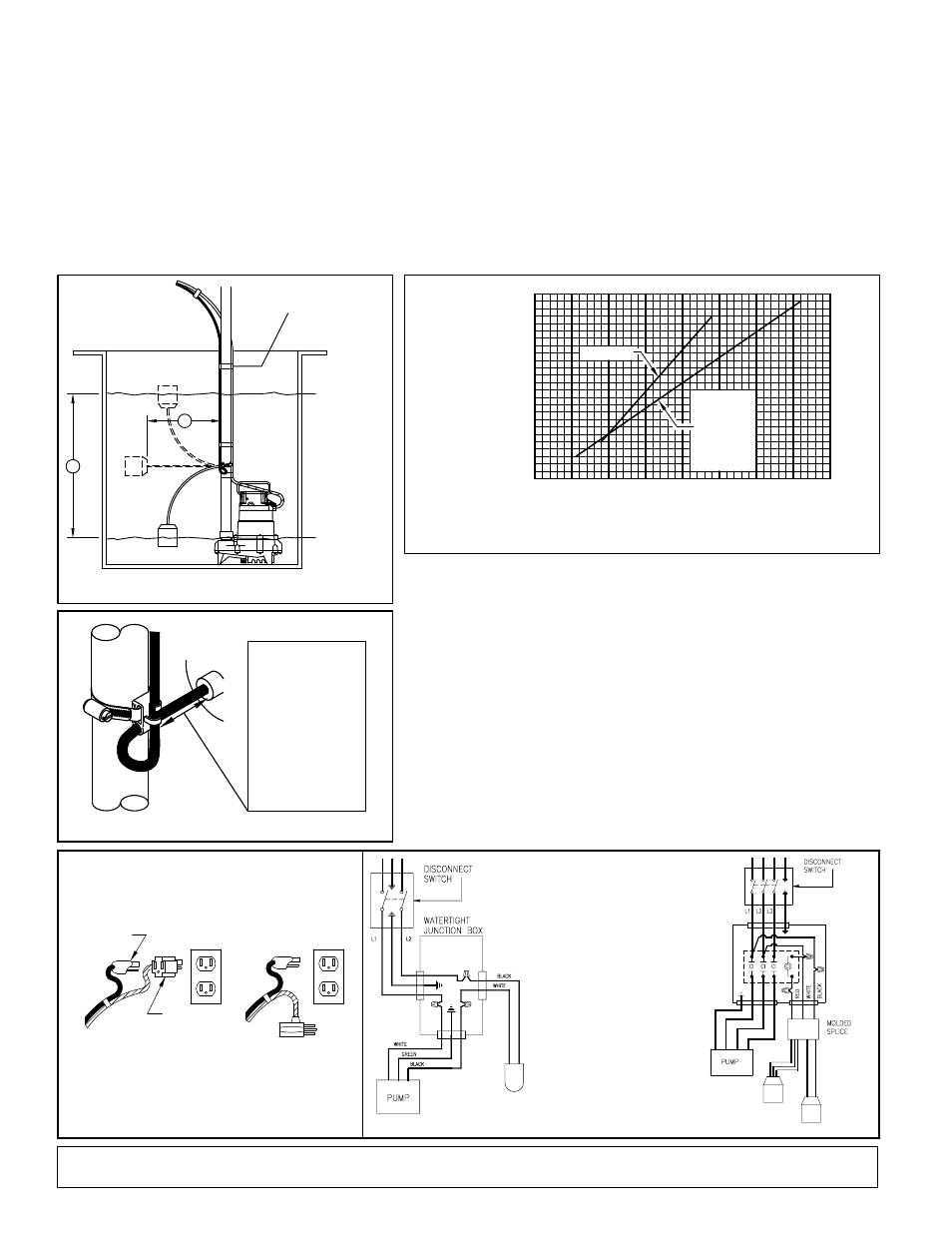
FIGURE 5
FIGURE 7
FIGURE 9
FIGURE 6
A) Remove (cut) Piggyback
Plug from Variable Level
Pump switch. Remove
approx. 3½” of cord
jacket and 1” insulation
from wires.
b) Wire switch into circuit as
shown.
C) Return to instructions.
D) Installation must be
in agreement with the
National Electrical Code
and all local codes.
FIGURE 8
(b)
DIsTANCE
FROM MOUNTING
CLAMP TO FLOAT
IN INCHEs
NOTE: Measurements as shown are approximate.
Exact measurements to be determined for each
individual installation.
(A)
PUMPING RANGE
IN INCHES
iNstallatioN iNstrUctioNs
1. Decide the desired pumping range for your installation instruction. (See Fig.5 and Figure 10.) (B) is the
distance between the mounting point of attachment and the float. The distance (B), determines (A), the
desired pumping range.
2. At Distance (B), determined from Figure 10) place the cord into the clamp as shown in Fig. 6.
3. Position the float to the desired “OFF” level and secure the clamp to the discharge pipe as shown in Fig.6.
See Fig. 5 noting water line. NOTE: Do not install cord under hose clamp.
4. Tighten hose clamp using a screw driver. NOTE: Do not over tighten. Over tightening may result in
damage to the plastic clamp. Make sure the float cable is not allowed to touch the excess hose clamp
band during operation.
Notice: Do not adjust “off’’ level below discharge on pump.
5. Insert the piggyback plug from the switch into a standard grounded outlet of proper voltage. For automatic
operation, plug the pump directly into the piggyback plug. (See Fig. 7.) Pump can be manually operated
by bypassing the piggyback plug.
Notice: For installation utilizing watertight junction box or similar connections, see Figure 8.
Notice: For installation as a control switch for magnetic starter, see Figure 9.
6. Tape or clamp both piggyback switch and pump cords to the discharge pipe, clear of float operation. (See
Fig. 5.) Excess cord should be coiled and fastened outside the basin.
7. Clean basin free of debris after installation.
8. Check your installation. Fill basin with water and allow pump to cycle to insure proper range and operation.
Clarus Environmental Variable Level Pump Switches are designed for use with the appropriate voltage and horsepower, nonautomatic, single phase, Clarus
Environmental pumps. Maximum liquid temperature must not exceed 120°F for 10-0748.
Clarus Environmental Variable Level Pump Switches can be used as a control switch for a magnetic or combination starter. Maximum temperature must not exceed
140° F. See figure 9.
Single Variable Level Pump Switches are recommended for use in 18” minimum diameter pits or basins.
Note: Consult Clarus Environmental for controlling units over 1½ HP with a variable level pump switch.
sk1301D
FIGURE 10
3.5 INCH
TETHER LENGTH
FOR DOUBLE
FLOAT
3.5 INCH
MINIMUM
TETHER LENGTH
FOR PUMP
SWITCH
25
40
35
30
25
10
5
15
20
0
20
15
5
10
P/N 10-0033
P/N 10-0034
P/N 10-0055
P/N 10-0032
P/N 10-0035
P/N 10-0706
P/N 10-0559
P/N 10-0705
P/N 10-0063
P/N 10-0748
sk1299
PUMP PLUG
SWITCH PLUG
AUTOMATIC
OPERATION
MANUAL
OPERATION
sk308A
VARIABLE
LEVEL
PUMP
SWITCHES
sk378A
VARIABLE
LEVEL
PUMP SWITCH
sk306A
A
B
"ON"
LEVEL
"OFF"
LEVEL
CORDS SECURED TO
DISCHARGE PIPE
sk305b
All Clarus Environmental products must be installed and maintained in accordance with all applicable codes.
Product information presented here reflects conditions at time of publication. Consult factory regarding discrepancies or inconsistencies.
10-0055 - 115V/Max. ½ HP 13A 10’ cord*
10-0032 - 115V/Max. 1 HP 15A 15’ cord*
10-0033 - 230V/Max. 2 HP 15A 15’ cord*
10-0034 - 115V/Max. ½ HP 13A 15’ cord*
10-0035 - 230V/Max. 1 HP 13A 15’ cord*
*for EFFLUENT, SEWAGE and DEWATERING (120°F Maximum Liquid Temperature)
10-0063 - 115V/Max. ½ HP 13A 20’ cord*
10-0559 - 230V/Max. 2 HP 15A 20’ cord*
10-0705 - 115V/Max. ¾ HP 15A 20’ cord*
10-0706 - 230V/Max. 1 HP 13A 20’ cord*
10-0748 - 230V/Max. 3 HP 20A 25’ cord* (No Plug)