The carlin model 702gas gas burner – Carlin 702GAS Supp. User Manual
Page 3
Model 702GAS Advanced gas burners — Supplement 1 – Massachusetts Code
Carlin part number MN702GM Rev. 11/18/08
– 3 –
Where appliance instructions differ from this manual, follow the appliance instructions.
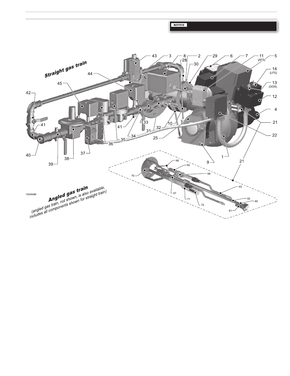
1. The Carlin Model 702GAS gas burner
(continued)
1
Cast aluminum burner housing
2
Air tube (with gas manifold)
3
Burner flange
4
Burner motor
5
Primary control, Honeywell RM7897C
6
Carlin EZ-Contactor (burner motor contactor)
7
Ignitor (Carlin 41000)
8
Damper motor
9
Air damper & low fire adjusting screw
10
Air damper linkage
11
Air flow switch (AFS)
12
Junction box (connection for 120
vac
power and
120
vac
control and limit circuit input from boiler)
13
ON/OFF switch
14
Low fire hold switch (LFS)
21
Combustion head assembly
22
Air flow switch J box
28
Pilot Orifice Nipple
29
Gas manifold
30
Gas spuds (4 required)
31
Gas butterfly valve
32
Butterfly valve linkage
33
Union
34
Gas shut-off valve (with test tapping)
35
Automatic gas valve (diaphragm type)
36
Automatic gas valve
37
Gas train junction box
38
Gas pressure regulator
39
Manual gas valve (with two test tappings)
40
Gas entrance connection
41
Pressure tap & bleed port
42
Pilot gas line manual valve (with 2 test tappings)
43
Combination pilot gas valve
44
High gas pressure switch, manual reset
45
Low gas pressure switch, manual reset
60
Head position indicator scale
61
Head position adjustment screw
62
Support rod
63
Electrode lead wires
64
Thermal fuse
65
Electrode ceramic insulators
66
Electrodes
67
Electrode clamp70 Retention ring assembly
70
Retention ring assembly
71
UV scanner tube/adapter
72
UV scanner
Replace Instruction manual content:
This page replaces Instruction manual page 5.