Prepare site • prepare burner • mount burner, Prepare burner and components, Model 201gas burner — instruction manual – Carlin 201GAS User Manual
Page 7
Model 201GAS burner — Instruction manual
Carlin part number MN201GAS Rev. 03/14/11
– 7 –
Where appliance instructions differ from this manual, follow the appliance instructions.
1. Prepare site • prepare burner • mount burner
(continued)
Prepare burner and components
Do not install or operate the burner if any component is damaged
or if burner does not comply with the specifications of Table 1
and other guidelines in this manual.
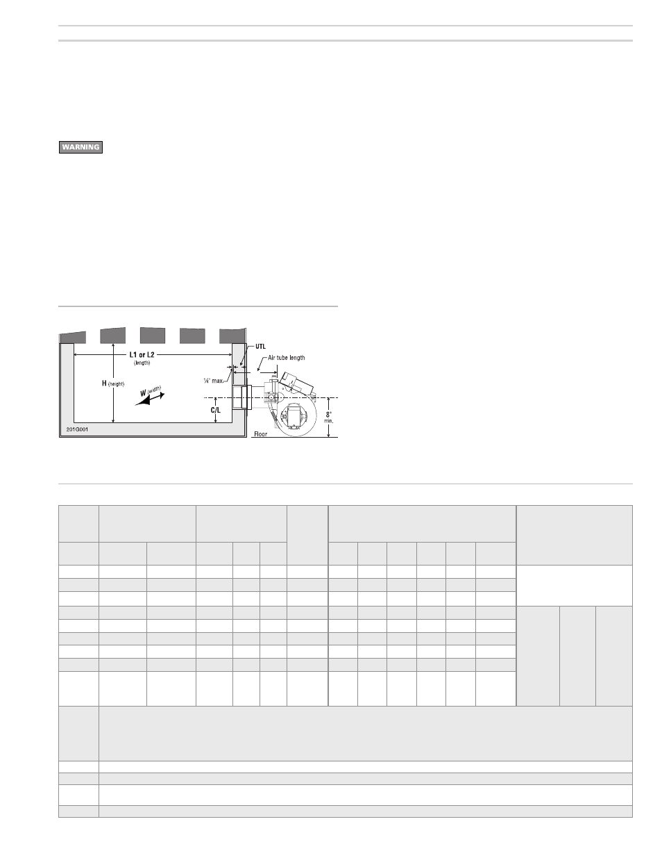
Air tube insertion length (UTL)
• Usable air tube length (UTL) is the distance from mounting flange to end
of air tube. Verify that the end of the air tube will be flush with, or no more
than ¼ inch short of, the inside of the appliance combustion chamber
front wall when the burner is mounted. See Figure 3 and Table 1 below,
for further information.
Diffuser plate
• Verify correct diffuser plate (item 2, page 3). Compare diffuser plate listed
on air tube label with diffuser plate listed in Table 1.
Figure 3 Combustion chamber dimensions (see Table 1)
Gas orifice drill size
• The gas orifice is drilled through a plate in the end of the orifice nipple
(see item 8, page 3). Read the factory-drilled orifice size on the label
attached to the burner air tube (see item 1, page 3) near the blower
housing end. If the gas orifice size is not correct for your application,
or if the label is illegible for any reason, check the orifice size directly
and redrill orifice or replace if necesary, as follows (next page).
Table 1 Burner specifications for 201GAS burners
Input
Note 1
Burner orifice
drill size
Approximate
air band setting
Notes 1 & 2
Diffuser
Minimum chamber dimensions
Inches (Notes 3, 4, 5)
(VC = min. diam. of vertical cylinder chamber)
UTL
Air tube
insertion length
Btuh
Natural
gas
Propane
gas
%
Slots
Air
shutter
C/L
L1
L2
W
H
VC
150,000
9/32
7/32
15
2
Yes
C
4
11
14
8
10
9½
Burners with welded flange have fixed
usable tube length (UTL). Verify length
is correct for the application. Burners
with adjustable flange: Usable tube
length (UTL) varies with air tube length:
175,000
5/16
1/4
30
2
Yes
C
4
12
16
8
10
10
200,000
11/32
9/32
60
2
Yes
C
4½
14
17
8
11
12
225,000
11/32
9/32
8
2
No
B
4½
15
18
9
11
13
Nominal
air tube
length
----------
8”
10”
12”
14”
16”
UTL
min.
---------
1 ¾”
1 ¾”
1 ¾”
1 ¾”
1 ¾”
UTL
max.
---------
2 ½”
4 ½”
6 ½”
8 ½”
10 ½”
250,000
3/8
5/16
25
2
No
B
4½
16
19
9
11
14
275,000
13/32
5/16
40
2
No
B
4½
17
21
10
11
15
300,000
13/32
5/16
15
4
No
A
5
17
21
12
12
15
350,000
15/32
11/32
35
4
No
A
5½
17
21
12
12
15
399,000
9/16
7/16
80
4
No
A
6
20
24
14
13
17
Note 1
High altitude applications: The maximum burner input at sea level is 399,000 Btuh. Reduce this capacity by 4% per 1,000 feet above sea level. Example — max.
capacity at 5,000 feet is 319,000 Btuh (20% reduction).
Pressurized firing: Maximum burner input decreases with increasing overfire pressure. Assume a reduction in maximum burner input of approximately 5% at 0.1
inches w.c. and 10% at 0.2 inches w.c. You will have to increase the air band opening to compensate for the increased pressure. Follow the procedures given in
this manual to check combustion with instruments to determine the correct air band setting. Do not fire into a chamber with pressure higher than 0.2 inches w.c.
and never fire at a higher pressure than recommended by the appliance manufacturer.
Note 2
Use this as the starting setting only. Adjust air band setting, if necessary, after performing combustion testing (see page 13).
Note 3
Some tested appliances may operate satisfactorily with dimensions less than the above.
Note 4
Horizontal cylindrical chambers — diameter must be no less than column “W” above
Horizontal stainless steel cylindrical chambers — diameter at least 1 to 4 inches larger than column “W” above.
Note 5
A corbel may help heat transfer in a larger boiler or furnace, provided it is recommended by the appliance manufacturer.