Check system • start-up burner/appliance, Start-up & operation – Carlin 601GAS Mass Code Supp. User Manual
Page 6
Model 601GAS burner — Instruction manual — Supplement – Massachusetts Code
Carlin part number MN601GASM Rev. 05/01/07
– –
Where appliance instructions differ from this manual, follow the appliance instructions.
Replace Instruction manual content:
This page replaces Instruction manual page 17.
Should overheating or an emergency occur, immediately:
• Shut off main manual gas valve.
• Shut off control switch to burner.
Under some circumstances power should remain on for
circulating blowers or other equipment. Determine proper
response before attempting start-up.
If burner fails ignition on several attempts, close gas valve
and use burner blower to purge appliance before restart.
4. Check system • start-up burner/appliance
(continued)
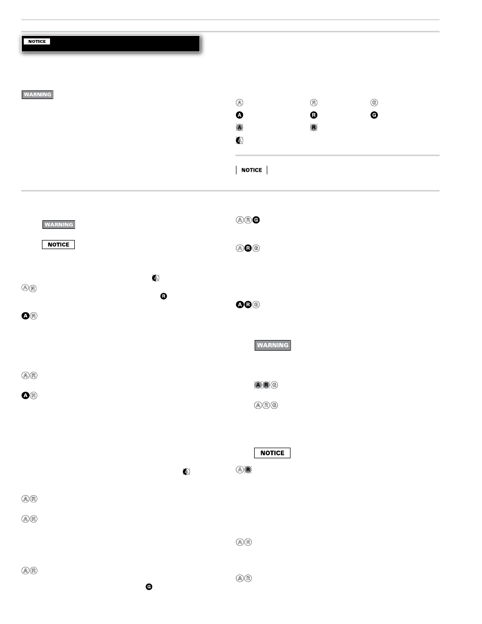
Model 60200FR diagnostic LED’s
– Amber OFF
– Red OFF
– Green OFF
– Amber ON
– Red ON
– Green ON
– Amber FLASHING
– Red FLASHING
– Amber BLINKING (blinks off momentarily every 3 to 4 seconds)
Please see 60200FR control label for trial for ignition (TFI)
and purge timings.
Start-up & operation
(Massachusetts Code burners)
Do not start the burner if the combustion chamber
contains residual gas. Allow gas to disperse.
Per UL requirements, the control will not turn on if the
flame rod senses flame during the self-test. If the flame
rod senses flame, the green LED turns on. The control
will remain in self-test mode until the flame rod no
longer senses flame. The amber LED will remain on,
but blink off momentarily every 3 to 4 seconds.
Run
The burner continues firing during call for heat if the
flame rod senses flame. Amber and red LED’s are off
and green LED is on during normal running.
Lockout If the flame rod does not sense flame within the TFI
time limit after gas valve activation, lockout occurs.
The control turns the red LED on constant, and closes
the alarm contact. Green LED is off.
To
Reset Push in and hold reset button for 1 second, then re-
lease.
Latch-up If the control locks out 3 times during a single call for
heat, latch-up occurs. The control turns on both the
amber and red LED’s constant. You must use the special
procedure below to reset the control after latch-up.
Reset from latch-up — Only a qualified service
technician should attempt to reset the control
after latch-up. The problem that caused the re-
peated burner problems must be corrected before
returning the burner to normal operation.
Push in and hold the reset button for about 10 seconds.
The red and amber LED’s will flash alternately.
After the LED’s begin flashing, continue to hold the
reset button for about another 20 seconds. The LED’s
will turn off. Release the reset button and the control
will restart. (Releasing the button before the LED’s turn
off will cause the control to remain in latch-up.)
The 60200FR control will not reset from lockout or
latch-up if power is interrupted.
Flame failure If the flame rod loses flame signal during operation
(after the TFI), the control enters lockout. The control
turns the red LED on constant, and closes the alarm
contact. Green LED is off.
To Reset Push in and hold reset button for 1 second, then release.
The burner will restart after reset. If the burner enters
lockout 3 times during a call for heat, Latch-up occurs.
See discussion above regarding Latch-up.
Post-purge Set operating control(s) and limit(s) to stop call for
heat. The gas valve will turn off within 2 seconds.
The motor remains on for the post-purge period, then
turns off.
Stand-by
Control remains in stand-by mode until limit circuit
sends power to the black wire and thermostat circuit
closes (or jumpered) — (call for heat).
Power ON Open all manual gas line valves. Close the line switch.
(If Red LED turns on constant , control is in lockout.
See below to reset.)
Self-test 1 The control performs a “boot-up” test to verify internal
operation each time power is applied to the red/white
wire. About 4 seconds after power application, the
amber LED turns on. The test continues for about 6
more seconds. If the test fails, the control turns the
amber LED off and repeats this test sequence until
successful.
Stand-by
(No call for heat) If Self-test 1 is successful, amber LED
turns off and control waits for heat call.
Call for heat Set operating control and all limit controls to call for
heat. The 60200FR thermostat circuit must be closed
(jumpered) and power coming to black wire from lim-
its.
Self-test 2 The amber LED turns on. For the first 3 to 4 seconds,
the control performs a self-test. If the flame rod senses
flame, the green LED turns on. The control repeats the
self-test until flame is no longer detected (green LED
would turn off). During this time, the amber LED will
remain on, but blink off momentarily every 3 to 4
seconds. If the control detects motor contacts closed
or power to the gas valve, lockout occurs.
Burner on
After the self-test, the amber LED turns off. The motor
starts.
Pre-purge
The ignitor starts after the pre-purge period. Two
seconds later, the
two-stage gas valve is activated
for low fire. The burner starts at a low fire rate. After
8 seconds, the time-delay relay closes, powering the
two-stage gas valve’s second stage. The burner goes
to high fire.
TFI
After the gas valve is activated, the flame rod must
sense flame within the TFI time limit (trial for ignition).
The green LED turns on at the end of the TFI if the
flame rod senses flame.