Dimension and mounting information, Model 301gas burner — instruction manual, Mounting burner to appliance – Carlin 301GAS Inst Manual User Manual
Page 19
Model 301GAS burner — Instruction manual
Carlin part number MN301GAS Rev. 03/14/11
– 19 –
Where appliance instructions differ from this manual, follow the appliance instructions.
8. Dimension and mounting information
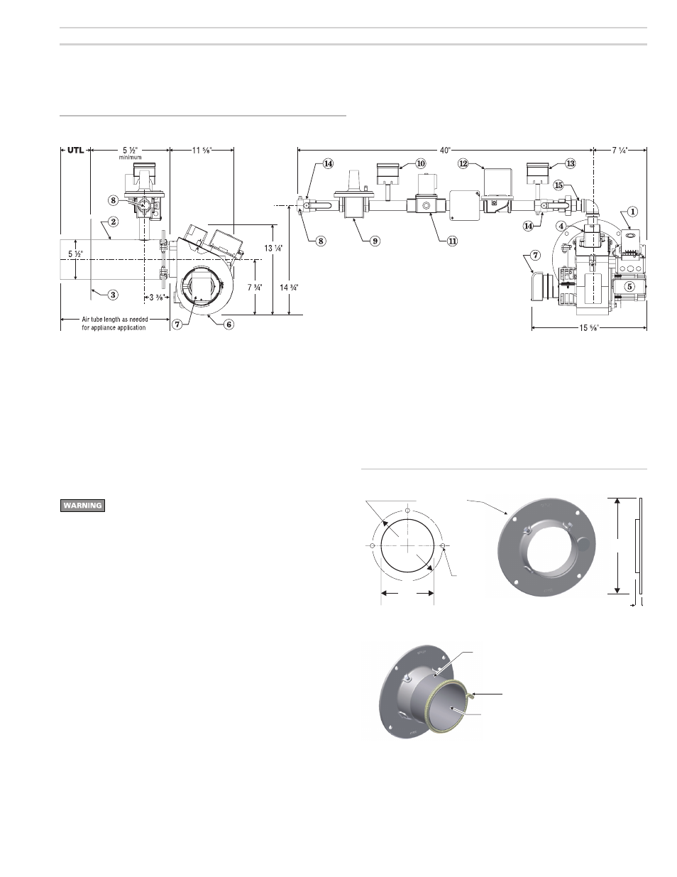
Figure 13
Dimensional data
Mounting burner to appliance
Positive overfire pressure applications: When firing with posi-
tive overfire pressure, do not exceed the pressure specified
in the appliance manual.
Positive overfire pressure reduces maximum burner capacity.
See Table 1 notes for estimated reduction in burner capacity
with pressurized firing.
When using the adjustable flange, follow the steps in Figure 14
to prepare for pressurized firing.
Failure to comply could result in severe personal injury, death
or substantial property damage.
When using a welded flange burner, verify the insertion depth on the ap-
pliance and burner (see page 7).
If using the adjustable flange (Figure 14), measure the appliance insertion
depth to the set the position of the flange on the air tube. Tighten the flange
locking screws firmly. Prepare the appliance opening to the dimensions
shown in Figure 14. Also read page 7.
Figure 14
Adjustable flange mounting information
30117
5½"
2¹⁄₂
"
11"
Bolt circle: 10"
Appliance burner opening
Forced draft flange
Drill & tap
3 holes –
– 16
³⁄₈
Fiberglass sealing rope, 1/4" diameter
Pack sealing rope into counterbore of forced draft flange,
overlapping the rope to ensure a complete seal.
Burner air tube
1 Carlin 60200 primary
2 Air tube
3 Flange (welded shown)
4 Carlin 41800 ignitor
5 Carlin PSC motor
6 Cast aluminum housing
7 Air flow switch
8 Gas connection, 1” NPT
9 Gas pressure regulator
10 Low gas pressure switch
11 Secondary gas valve
12 Primary gas valve
13 High gas pressure switch
14 Manual gas cocks
15 Orifice nipple