Circuit diagrams, On 7.0) w – Carbolite RWF Series User Manual
Page 12
CWF, BWF, RWF
12
MF02 – 3.19
7.0 C
IRCUIT
D
IAGRAMS
EMC Filters (if fitted): dependent on the model there may be one filter, or more than one fitted in
parallel. The circuit diagram examples do not show multiple filter arrangements.
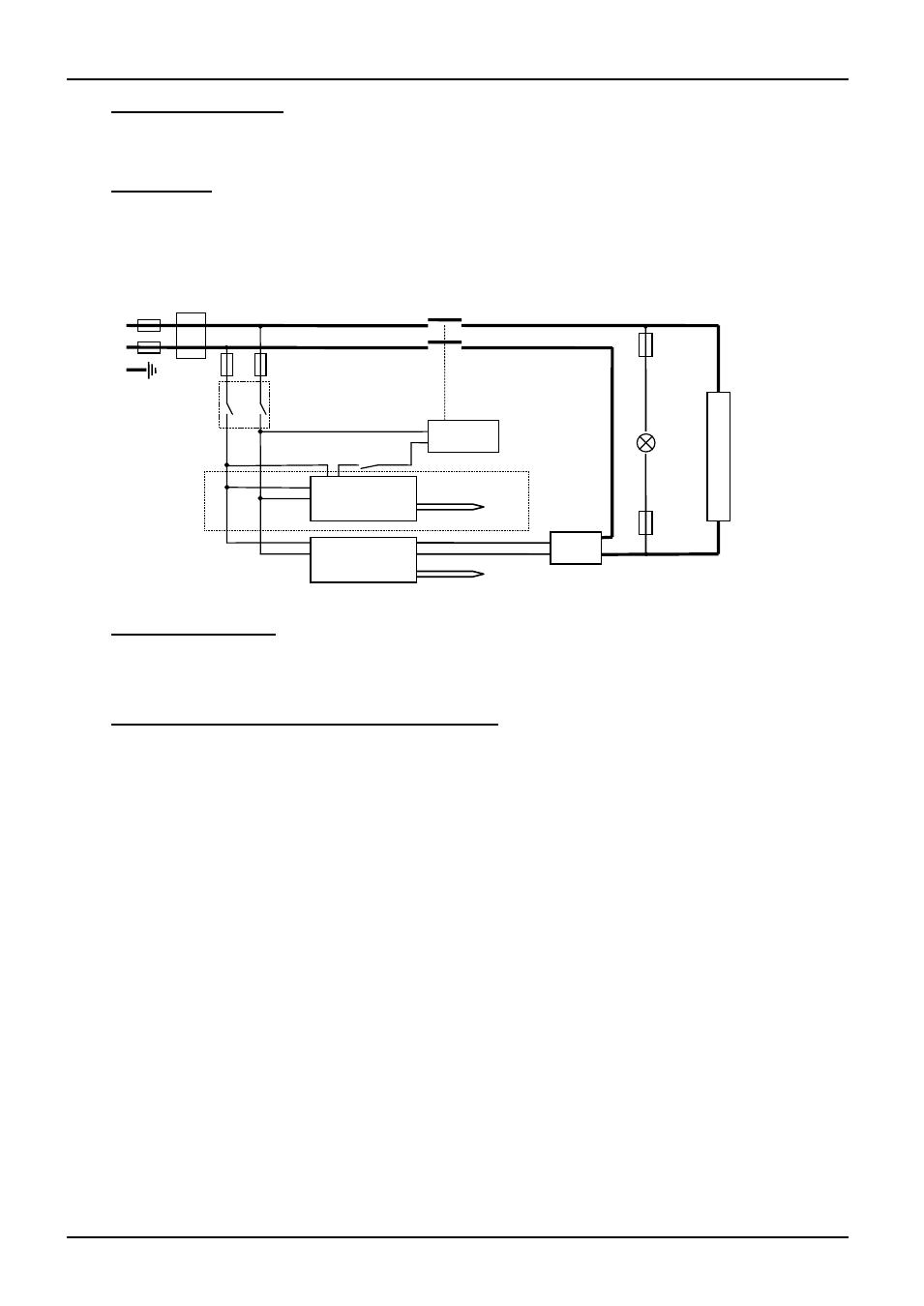
7.1 Single Phase
NOTE – year 2001 onwards: single phase model --/23 replaced by Universal model – see 7.4.
NOTE – models before mid-2002: in some models two door switches were fitted directly in the
element circuit, instead of a single switch and contactor.
7.2 2-phase with neutral
Please enquire if a diagram is required.
7.3 Higher Voltages (e.g. 254V; 440V, 480V 3-phase)
The diagram above (7.5) normally applies, with neutral (if present) not being used.
For single phase models of 254V or above, diagram 7.1 or 7.4 applies except that a control circuit
transformer is included as in diagram 7.5.
Instrument Switch
coil
temperature
controller
overtemp.
controller
door
switch
SSR
e
l
e
m
e
n
t
(s)
heat
on
F3
F1
F2
F3
N
L
PE
Filter (if fitted)
contactor
or relay
if fitted
thermocouple
thermocouple