Installation instructions – Blue Sea Systems 7620 ML-ACR Automatic Charging Relay - 12V DC 500A User Manual
Page 3
REMOTE (Red)
A
B
LED
(Yellow)
ISOLATION #1 (Brown)
GROUND (Black)
LED
1
2
START
BATTERY
ENGINE
ML-SERIES
REMOTE
BATTERY
SWITCH
HOUSE
BATTERY
HOUSE
DISTIBUTION
ISOLATION #2 (Green)
ISOLATION #3 (Orange)
2 AMPS
ENGINE
START
SWITCH
ON
OFF
START
3
+8
-7
ENGINE
ENGINE
START SWITCH
ON
OFF
START
ML-SERIES
REMOTE
BATTERY
SWITCH
ML-SERIES
AUTOMATIC
CHARGING
RELAY
LED
NOTE: The remote
switch has two LEDs.
These LEDs operate
simultaneously and
are either both ON
or both OFF.
NOTE: Use circuit protection
only if ACR is not used for
emergency cross-connect.
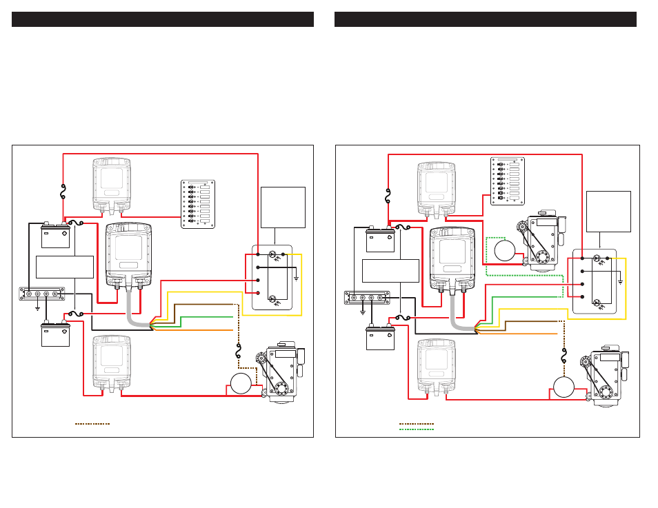
Engine Isolation
The ML-Series ACR can be configured to automatically open when two engines are simultaneously running
to ensure that two running engines are never electrically connected. Enable this feature to reduce
noise and communication cross-talk between engines, and to maximize total potential alternator output.
To enable Engine Isolation for two engines:
• Connect the brown wire (ISOLATION #1) from the harness to the ON terminal of the start key switch on
one engine. Make this connection through a 2 Amp in-line fuse. This connection must be to the line that
is positive while the engine is normally running.
• Connect the green wire (ISOLATION #2) to ENGINE #2 in the same manner as above.
To enable Engine Isolation for three engines:
• Connect the brown wire (ISOLATION #1) to ENGINE #1, the green wire (ISOLATION #2) to ENGINE #2, and
the orange wire (ISOLATION #3) to ENGINE #3 in the same manner as above.
990180180 Rev.004
page 3 of 4
REMOTE (Red)
A
B
LED
(Yellow)
ISOLATION #1 (Brown)
GROUND (Black)
LED
1
2
START
BATTERY
ENGINE
ML-SERIES
REMOTE
BATTERY
SWITCH
ML-SERIES
REMOTE
BATTERY
SWITCH
HOUSE
BATTERY
HOUSE
DISTRIBUTION
ISOLATION #2 (Green)
ISOLATION #3 (Orange)
2 AMPS
ENGINE
START
SWITCH
ON
OFF
START
ML-SERIES
AUTOMATIC
CHARGING
RELAY
3
+8
-7
LED
NOTE: The remote
switch has two LEDs.
These LEDs operate
simultaneously and
are either both ON
or both OFF.
NOTE: Use circuit protection
only if ACR is not used for
emergency cross-connect.
Installation Instructions
Start Isolation
The ML-Series ACR can be configured to automatically open temporarily (3-5 minutes) when voltage is
sensed on any one of up to three start-isolation inputs. Enable this feature to isolate Start circuits from the
House circuit and prevent starting current transients from interfering with sensitive house electronics.
To enable Start Isolation:
• Connect the brown wire (ISOLATION #1) from the harness to the terminal or wire running from the start
key switch to the starter solenoid. Make this connection through a 2 Amp in-line fuse. This connection
can be made at the start key switch or at the starter solenoid, but must be to the line that is positive only
when cranking the engine. as shown below.
To enable Start Isolation for two or three engines starting from the same battery:
• Connect the green wire (ISOLATION #2) to ENGINE #2 in the same manner as above.
• Connect the orange wire (ISOLATION #3) to ENGINE #3 in the same manner as above.
Start Isolation Installation
Installation Instructions
(continued)
Engine Isolation Installation
Legend
Optional connection
Legend
Optional connection