BernzOmatic GRA-200 User Manual
Stage propane regulator with pol connection, Regulador de propano de 2 etapas con conexión pol, Instruction manual gra-200
DANGER
Failure to comply with these Warnings and Instructions
may result in an explosion or fire that may cause
property damage, serious personal injury or death.
PELIGRO
Si no se cumplen estas advertencias e instrucciones,
se pueden producir una explosión o un incendio que
pueden causar daños materiales, lesiones personales
graves o la muerte.
ADVERTENCIA
• Para gas LP únicamente.
• Lea todas las instrucciones antes de instalar y usar.
• La desconexión del regulador/conjunto de la manguera y la prueba de
fugas deben realizarse al aire libre en un área bien ventilada.
• NO modifique este regulador. Si este regulador no calza, devuélvalo
al lugar de compra original y obtenga el regulador correcto para su
artefacto a gas.
• Examine el regulador, la manguera y los adaptadores nuevos para
verificar que no estén dañados. Si estuvieran dañados, devuélvalos al
lugar original de compra.
• Sólo debe moverse el artefacto a gas, quitarse el regulador viejo e
instalar un nuevo regulador cuando el artefacto esté frío.
• La presión de salida del regulador está configurada de fábrica. NO
intente ajustar ni reiniciar el regulador. Consulte a su proveedor local
• DO NOt use appliance until leak testing is complete and any leaks
are corrected.
de gas LP o técnico de servicio de gas LP si cree que el regulador no
está funcionando correctamente.
• NO use el artefacto hasta que se finalice la prueba de fugas y se
corrija cualquier fuga presente.
WARNING
• For LP-Gas Only.
• Read all instructions prior to installation and use.
• Disconnection of regulator / hose assembly and leak testing shall
take place outdoors in a well ventilated area.
• DO NOt make modifications to this regulator. If this regulator does
not fit, return it to the original place of purchase and obtain the
correct regulator for your gas appliance.
• Examine the new regulator, hose and fittings for damage.
If damaged, return to the original place of purchase.
• Movement of the gas appliance, removal of old regulator and
installation of new regulator shall only be done when appliance is
cool.
• the regulator outlet pressure is factory set. DO NOt attempt to adjust
or reset regulator. Consult your local LP-Gas supplier or LP-Gas
Serviceman if you think the regulator is not working properly.
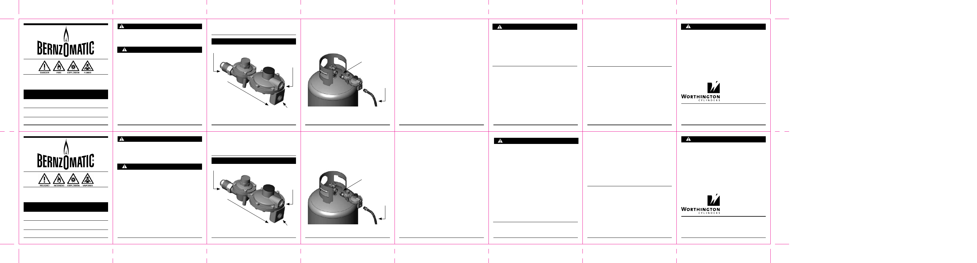
REGuLATOR INsTALLATION GuIDELINEs
1. turn gas off at cylinder by turning cylinder valve handle fully
clockwise.
2. Visually inspect hose from regulator to appliance for any indications
of wear or damage. If there are any signs of wear, damage or other
reasons why it may not be fit for continued service do not attempt to
reuse the hose. Purchase a new hose.
3. If the hose is fit for continued service, using a wrench, remove the
regulator from the cylinder in a clockwise motion (left-hand thread).
4. Using the proper size wrenches, remove the regulator from the hose.
Do not attempt to turn the hose when removing the regulator from the
hose. this will cause excessive twisting of the hose that may lead to
damaging or tearing the hose.
5. Clean the male threads on the hose fitting. Apply teflon
®
tape to the
male thread of the hose that will attach to the new regulator. Install
the regulator to the hose using the proper size wrenches.
6. Position the new regulator with the POL fitting on regulator inlet to
cylinder valve outlet. Connect to cylinder valve by turning the POL
fitting counter clockwise (left-hand thread) until hand tight. tighten
with the proper size wrench.
PAuTAs DE INsTALACIóN DEL REGuLADOR
1. Cierre el paso de gas en el cilindro girando la manija de la válvula del
cilindro totalmente hacia la derecha.
2. Inspeccione visualmente la manguera del regulador al artefacto
para detectar cualquier indicación de desgaste o daño. Si hubiera
cualquier signo de desgaste, daño u otras razones por las cuales
podría no ser adecuado continuar con el uso, no intente volver a usar
la manguera. Compre una manguera nueva.
3. Si la manguera es apta para continuar siendo usada, con una llave,
quite el regulador del cilindro con un movimiento hacia la derecha
(rosca izquierda).
4. Usando llaves del tamaño correspondiente, quite el regulador de la
manguera. No intente girar la manguera cuando esté quitando el
regulador de la manguera. Esto hará que la manguera se gire de
forma excesiva, lo cual puede llevar a que se dañe o desgarre.
5. Limpie las roscas macho del adaptador de la manguera. Aplique
cinta teflon
®
a la rosca macho de la manguera que se conectará al
nuevo regulador. Instale el regulador a la manguera usando llaves del
tamaño correcto.
6. Coloque el nuevo regulador con el adaptador POL en la entrada del
regulador para la salida de la válvula del cilindro. Conecte a la válvula
del cilindro girando el adaptador POL hacia la izquierda (en sentido
antihorario) hasta que quede ajustado manualmente. Ajuste con una
llave del tamaño correcto.
2
3
4
5
6
7
8
WARNING
When leak testing the connection:
• Conduct leak test outdoors in a well ventilated area.
• Do not smoke.
• Do not use or permit sources of ignition in the area while conducting
a leak test.
• Do not use matches, lighters or flame to check for leaks.
• Do not use the appliance until any leaks are corrected.
LEAk TEsTING
1. Before lighting your appliance, check for leaks by applying a mild
soapy water solution to all connections. Slowly open the cylinder
valve and check for leaks. the appearance of bubbles indicates a
leak.
2. Repair any leaks prior to lighting your appliance. If you cannot stop
a leak by additional tightening of the connection, shut off the LP-Gas
supply at the cylinder valve and have an LP-Gas service person make
the needed repairs.
ADVERTENCIA
Cuando realice la prueba de fugas en la conexión:
• Realice la prueba de fugas al aire libre en un área bien ventilada.
• No fume.
• No use ni permita fuentes de ignición en el área mientras realiza una
prueba de fugas.
• No use fósforos, encendedores ni llamas para verificar si existen
fugas.
• No use el artefacto hasta que se corrija cualquier fuga existente.
PRuEbA DE fuGAs
1. Antes de encender el artefacto, verifique que no haya fugas aplicando
una solución de agua jabonosa a todas las conexiones. Abra
lentamente la válvula del cilindro y verifique que no haya fugas. La
aparición de burbujas indica una fuga.
2. Repare todas las fugas antes de encender el artefacto. Si no puede
detener la fuga ajustando más la conexión, cierre el suministro de gas
LP en la válvula del cilindro y pídale a un técnico de servicio de gas
LP que realice las reparaciones necesarias.
9
10
11
12
13
14
15
16
2-Stage ProPane regulator
WIth Pol ConneCtIon
INsTRuCTION MANuAL
GRA-200
DO NOT DISCARD THESE WARNINGS AND INSTRUCTIONS
www.bernzOmatic.com
regulador de ProPano de
2 etaPaS Con ConexIón Pol
MANuAL DE INsTRuCCIONEs
GRA-200
NO DESECHE ESTAS ADVERTENCIAS E INSTRUCCIONES
www.bernzOmatic.com
331376 11.04.11
COMPONENTs AND AssEMbLY
GAS FLOW
REGLATOR
VENT
CYLINDER CONNECTION
REGLATOR
OUTLET
COMPONENTs AND AssEMbLY
CYLINDER CONNECTION
HOSE TO
APPLIANCE
COMPONENTEs Y ARMADO
FLUjO DE GAS
SALIDA DEL
REGULADOR
CONExIóN DEL CILINDRO
VENTILACIóN
DEL REGULADOR
CONExIóN DEL CILINDRO
VENTILACIóN
DEL REGULADOR
200 Old Wilson Bridge Road
Columbus, OH USA 43085
(866) 928-2657
worthingtoncylinders.com
200 Old Wilson Bridge Road
Columbus, OH EE.UU. 43085
(866) 928-2657
worthingtoncylinders.com
fuNCIONEs DEL REGuLADOR
• El regulador de gas de dos etapas está equipado con un dispositivo
de liberación de presión integral que limita la presión de salida
máxima del regulador en (2) psig. en caso de presurización excesiva
debido a un mal funcionamiento del regulador. Si ocurre un exceso de
presurización, póngase en contacto con un técnico de servicio de gas
LP para que realice reparaciones y/o reemplazos.
• El regulador de dos etapas también está equipado con un dispositivo
de detección de exceso del flujo que restringirá el flujo de gas en
caso de un aumento de demanda del flujo debido a una ruptura de la
manguera o una desconexión accidental mientras el regulador está
en uso.
EsPECIfICACIONEs TéCNICAs
tipo de gas:
gas LP (propano líquido)
Presión de salida:
11 pulg. col. H2O
(28 mbares)
Presión de entrada (máx.):
250 psig (máx.)
(17.5 bares)
Cuerpo del regulador:
aluminio fundido a presión
Capacidad en BtU:
200,000 BtU/Hr
WARNING
• Materials used in construction of this devise may contain brass
(which may contain lead), a chemical known to the State of California
to cause birth defects or other reproductive harm.
• Compustion by-products produced when using this device contain
chemicals known to the State of Califonia to cause cancer, birth
defects, or other reproductive harm.
ADVERTENCIA
• Los materiales utilizados en la construcción de este dispositivo
pueden contener latón (que a su vez puede contener plomo), un
producto químico que el estado de California ha determinado que es
cancerígeno, produce defectos congénitos o produce otros daños al
sistema reproductivo.
• Los productos secundarios de la combustión que se producen al
usar este dispositivo contienen productos químicos que el estado
de California ha determinado que son cancerígenos o que producen
defectos congénitos u otros daños al sistema reproductivo.
REGuLATOR fEATuREs
• the two-stage gas regulator is equipped with an integral pressure
relief which limits the regulator outlet pressure to (2) psig, maximum,
in case of over pressurization due to regulator malfunction. If over
pressurization occurs, contact a qualified LP-Gas serviceman for
repairs and/or replacement.
• the two-stage regulator is also equipped with an excess flow device
that will restrict gas flow in the event of a sudden increase in flow
demand due to hose rupture or accidental disconnection while the
regulator is in use.
TEChNICAL sPECIfICATIONs
Gas type:
LP-Gas
Outlet Pressure:
11” W.C. (28mbar)
Inlet Pressure (Max.):
250 psig (max.)
(17.5 bar)
Regulator Body:
Aluminum Die Cast
BtU Capacity:
200,000 BtU/Hr