APG DCU-1100 user manual User Manual
Page 9
Rev. A2, 11/06
DCU-1104 and DCU-1108
9
Automation Products Group, Inc.
APG...Providing tailored solutions for measurement applications
Tel: 1/888/525-7300 • Fax: 1/435/753-7490 • www.apgsensors.com • [email protected]
• Wiring
RED ................... 10 - 30 VDC (24 VDC recommended)
BLACK .............. POWER SUPPLY GROUND
YELLOW ........... ANALOG GROUND
ORANGE ........... 4-20 mA ANALOG OUTPUT
BLUE ................. RELAY 1 COMMON
GRAY ................ RELAY 1 NORMALLY OPEN
PURPLE ............ RELAY 2 COMMON
BROWN ............. RELAY 2 NORMALLY OPEN
GREEN .............. CLOCK SYNCHRONIZATION
WHITE ............... DIGITAL OUT
SHIELD ............. TERMINATE AT POWER SOURCE *
• Cable is a 10 conductor with shield, 22 AWG, 6 ft. (1.83 m) length.
• Ground and Analog ground are connected internal to the DCU-11.
* Shield is not connected in the DCU-11 and should be grounded at the
power source.
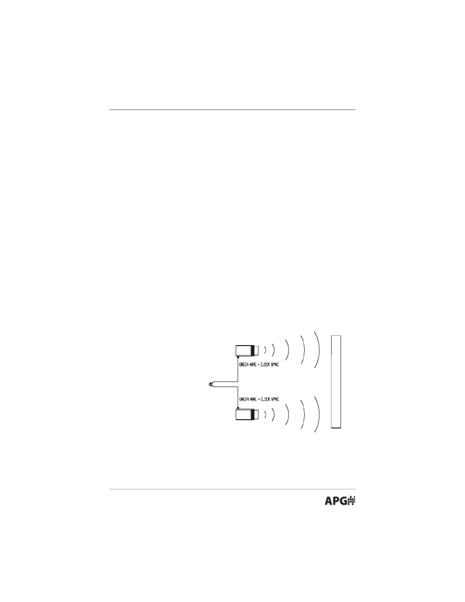
Wiring for Clock
Synchronization
The DCU-11 has the
capability to synchronize
the transmit pulses of
multiple sensors. When
sensors are mounted in
close proximity to one
another the sensors
should be synchronized to
help prevent cross talk
between sensors.
Wiring for a Digital
Out
The digital output is a pulse width signal which corresponds to the distance
being detected by the DCU-11 sensor. The digital signal is typically used in
conjunction with a APG (ACC-1007) or (ACC-1008) remote readout.