APG DCU-1100 user manual User Manual
Page 8
DCU-1104 and DCU-1108
Rev. A2, 11/06
8
Automation Products Group, Inc.
APG...Providing tailored solutions for measurement applications
Tel: 1/888/525-7300 • Fax: 1/435/753-7490 • www.apgsensors.com • [email protected]
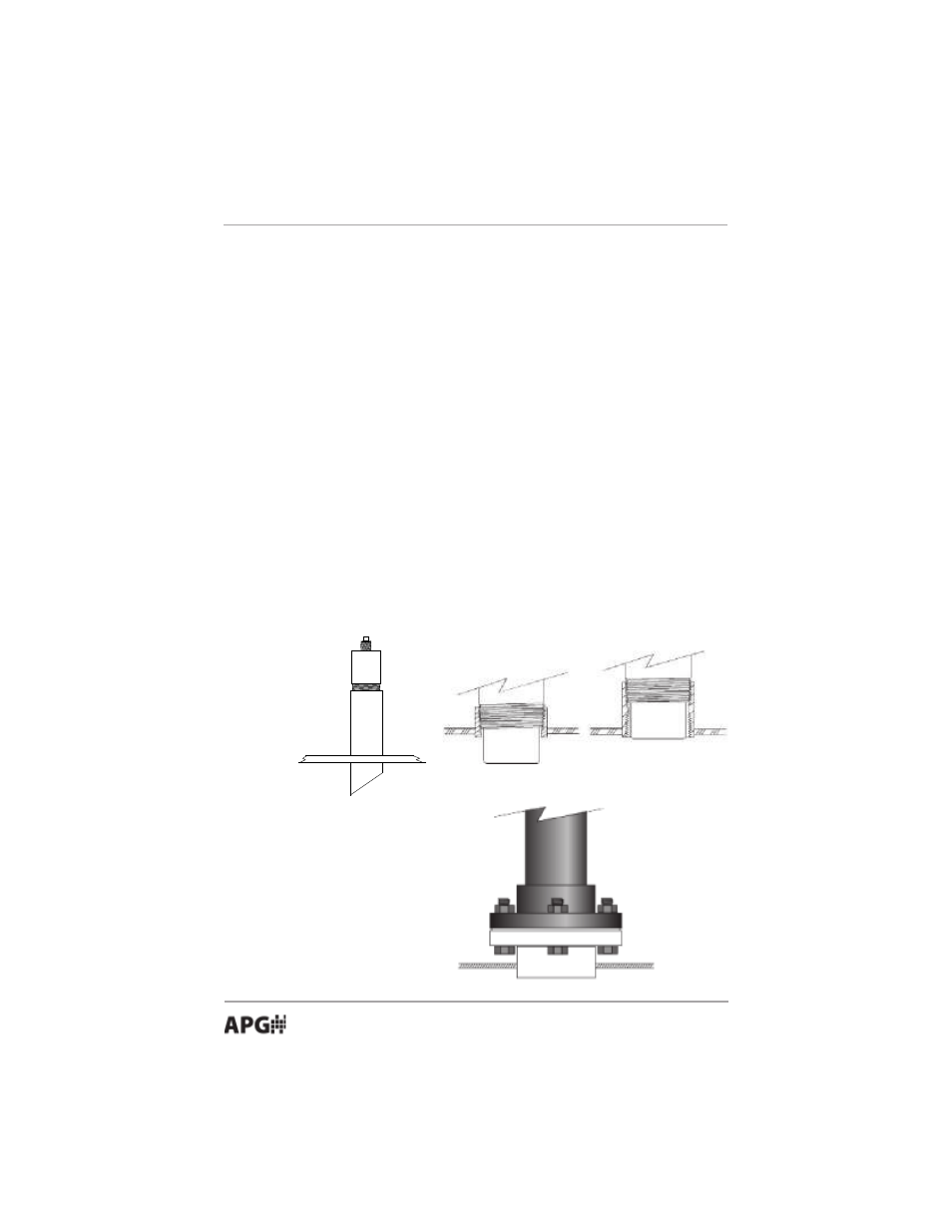
• Installation
The DCU-11 sensor should be mounted so that it has a clear sound path to
the level monitored. Mount the sensor away from tank walls and inlets. The
path should be free from obstructions and as open as possible for the 18° beam
pattern (9° off axis). Follow the guidelines mentioned in "Understanding
Ultrasonics", earlier in this manual. When using a stand pipe to mount the
sensor above the tank, the stand pipe should be seamless and no longer than 4
in. to provide a smooth path for the sound waves to propagate into the tank.
Seams from couplers, nipples or gaskets can cause erroneous echoes and
degrade the sensors performance.
The DCU-11 can be mounted in a coupler, or flange by using the 3 in.
threaded case. It can also be mounted using a Uni-Strut mounting bracket.
The minimum detection range of the DCU-11 is 2 ft. The sensor should be
mounted to ensure the target does not come closer than the minimum
range or erroneous readings may result.
To mount the DCU-11 for Class 1 Division 2 Groups A, B, C, and D, see the
Hazardous Mounting section of this manual.
*Soft gasket
material is
recommended with
flange mounting.
Top of Tank
Stand Pipe
10-45
o
CUT