Length of time for dcu-11 wiring diagram – APG DCU-1100 user manual User Manual
Page 10
DCU-1104 and DCU-1108
Rev. A2, 11/06
10
Automation Products Group, Inc.
APG...Providing tailored solutions for measurement applications
Tel: 1/888/525-7300 • Fax: 1/435/753-7490 • www.apgsensors.com • [email protected]
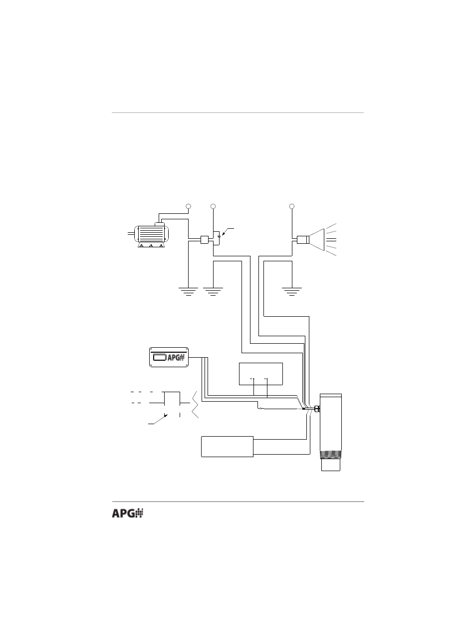
Wiring for a Relay Output
When switching a highly capacitive or inductive load, a swamping diode
should be used. This will protect the internal relay from possible damage and
prevent electrical noise from being introduced to the sensor which could result
in false readings.
RELAY
24 V DC
COIL
A.C.
24VDC
24VDC
Alarm
Gray (N.O.)
Blue (Common)
Brown (N.O.)
Purple (Common)
Swamping Diode
Power Supply
24VDC Neg.
White
Red 10-30VDC
Black Neg.
White Digital out
I/O Device
0 Volts
5 Volts
signal to travel from
transducer to target
and return to
transducer. The width
varies and is proportional
to the target distance.
Orange 4-20mA (+)
Yellow 4-20mA (-)
ACC-1008
Length of time for
DCU-11 Wiring Diagram
- LPU-2127 user manual (27 pages)
- LPU-2428 user manual (36 pages)
- MNU Modbus Sensor user manual (40 pages)
- LOE Tank Cloud Master Sensor user manual (36 pages)
- IRU-2000 datasheet (4 pages)
- IRU-3000 datasheet (4 pages)
- IRU-2000 user manual (42 pages)
- IRU-2420 datasheet (4 pages)
- IRU-3430 datasheet (4 pages)
- IRU-5000 datasheet (4 pages)
- IRU-6429 datasheet (4 pages)
- IRU-9400 datasheet (4 pages)
- IRU-3000 user manual (28 pages)
- DST Sensors datasheet (4 pages)
- PT-L1-C datasheet (4 pages)
- PT-L1-C user manual (8 pages)
- PT-L3-C user manual (8 pages)
- PT-L10-C user manual (8 pages)
- PT-L9 datasheet (4 pages)
- PT-L9 user manual (8 pages)
- PT-400 datasheet (4 pages)
- PT-400 user manual (17 pages)
- Hammer Union Pressure Tansmitter datasheet (4 pages)
- Hammer Union Pressure Tansmitter user manual (13 pages)
- PG5 datasheet (4 pages)
- PG5 user manual (28 pages)
- PG7 datasheet (4 pages)
- PG7 user manual (31 pages)
- PG10 datasheet (4 pages)
- PG10 user manual (42 pages)
- PT-500 datasheet (4 pages)
- PT-500 user manual (16 pages)
- PT-500 Modbus user manual (32 pages)
- PT-503 datasheet (3 pages)
- KA Cable Suspended datasheet (6 pages)
- KA Cable Suspended user manual (18 pages)
- FT-100 Cable Suspended datasheet (4 pages)
- FT-100 Cable Suspended user manual (8 pages)
- FL Series datasheet (4 pages)
- FLE Series user manual (12 pages)
- FLR Series user manual (28 pages)
- FLX datasheet (4 pages)
- FLX user manual (16 pages)
- LF Series datasheet (10 pages)
- LFE Series user manual (8 pages)