Expander disassembly – Allen&Heath GS1 SERVICE MANUAL User Manual
Page 9
ALLEN & HEATH
9
S1SM1
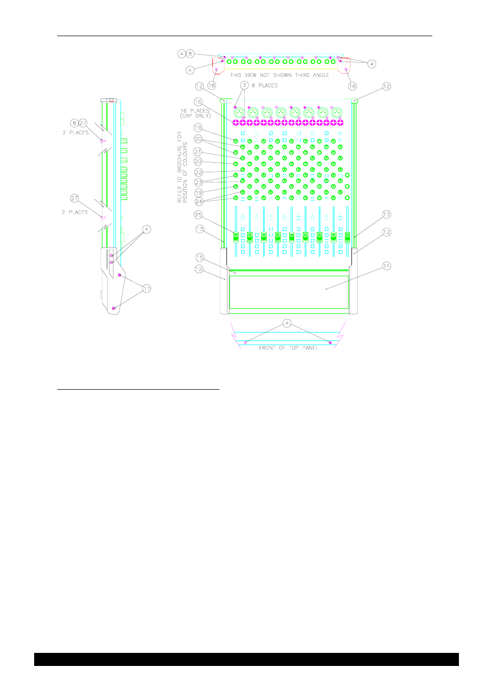
EXPANDER DISASSEMBLY
Stage 1 - Removing the front panel.
Refer to figure 3.
1.
Remove the 4x screws (27) and 2 shakeproof washers (8) from the underside of the side extrusions. (13)
2.
Remove the 4x screws (4) from the front end caps. (12)
3.
Remove the front extrusion (15) with the plastic front end caps (12) still attached.
4.
Remove the 2x screws (4) that attach the rear end caps (12) to the console chassis.
5.
Remove the side extrusions (13) with the end caps (12) still attached by sliding them to the rear.
6.
Remove the 8x fader knobs. (25)
7.
Remove the 88x rotary knobs. (19), (20), (21), (22), (23), (24).
8.
Remove 16x screws (3) from XLR connectors.
9.
Using a suitable coin remove the 16x plastic jack nuts (16) by rotating the nut 45 degrees counter-
clockwise.
10.
Working from the rear of the unit remove the 2x screws (4) and 1 shakeproof washer (8) that attach the
top panel to base.
11.
Working from the front of the unit remove the 2x screws (4) that attach the top panel to the base.
12.
You can now lift the top panel off.
Re-assembly is the reverse of the above procedure, taking care to ensure that LEDs and switch caps fit through the top
panel correctly.
side view
rear view
Figure 3.