Allen&Heath GS1 SERVICE MANUAL User Manual
Page 10
ALLEN & HEATH
1 0
S1SM1
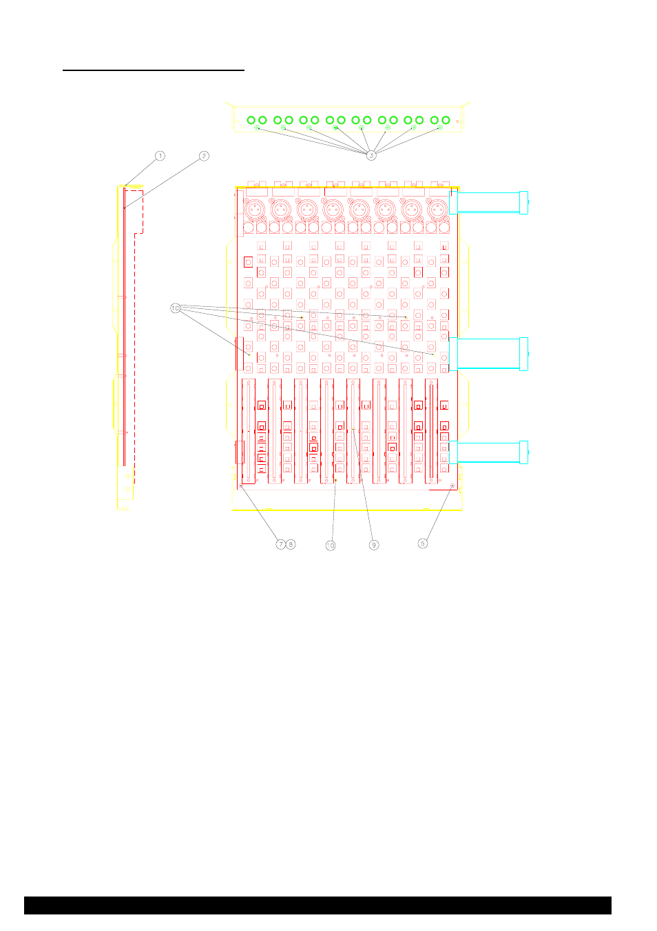
Stage 2 - Removing the PCB.
side view
rear view
Refer to figure 4.
1.
Remove the 8x screws (3) from the phono connectors along the rear panel.
2.
Remove the locknut (5) from the front right stud.
3.
Remove the nut (7) and shakeproof washer (8) from the front left stud.
4.
Carefully ease the PCB off the 6 plastic snap-in supports (10) by squeezing together top of supports with
pliers or suitable tool.
Re-assembly is the reverse of the above procedure taking care to push PCB down over all plastic snap-in supports.
Figure 4.
See also other documents in the category Allen&Heath Control panel:
- GL2800M SERVICE MANUAL (13 pages)
- GL2800M USER GUIDE (23 pages)
- 21 Series (18 pages)
- GL3800 (44 pages)
- Xone V6 (42 pages)
- Xone S6 (42 pages)
- Xone DX (67 pages)
- Xone 3D (42 pages)
- Xone 32 (25 pages)
- Xone 1D (2 pages)
- Xone 2D (34 pages)
- XB 14 (40 pages)
- WZ20 8 2 SERVICE MANUAL (35 pages)
- WZ16 2DX (28 pages)
- WZ16 2 (16 pages)
- WZ14-4-2 MK2 (24 pages)
- WZ14-4-2 (21 pages)
- WZ 20S USER GUIDE (35 pages)
- WZ 20S SERVICE MANUAL (23 pages)
- SR Plus OWNER MANUAL (1 page)
- Scepter SERVICE MANUAL (21 pages)
- Scepter USER GUIDE (42 pages)
- RPS9 (7 pages)
- RPS14 (18 pages)
- RPS10 (7 pages)
- ML5000 SERVICE MANUAL (135 pages)
- ML5000 SIDECAR USER GUIDE (4 pages)
- ML5000 USER GUIDE (60 pages)
- ML4000 USER GUIDE (4 pages)
- ML4000 USER GUIDE (56 pages)
- ML4000 SERVICE MANUAL (91 pages)
- ML3000 Application Guide (2 pages)
- ML3000 USER GUIDE (48 pages)
- ML3000 Using Guide (2 pages)
- ML3000 VCA (3 pages)
- MixWizard3 16-2 (30 pages)
- MixWizard3 14-4-2 (27 pages)
- MixWizard3 12M (22 pages)
- GS3000 (40 pages)
- GS1 USER GUIDE (22 pages)
- GR8A (11 pages)
- GR1 USER GUIDE (17 pages)
- GR1 SERVICE MANUAL (48 pages)
- GL4800 USER GUIDE (62 pages)