Allen&Heath GS1 SERVICE MANUAL User Manual
Page 32
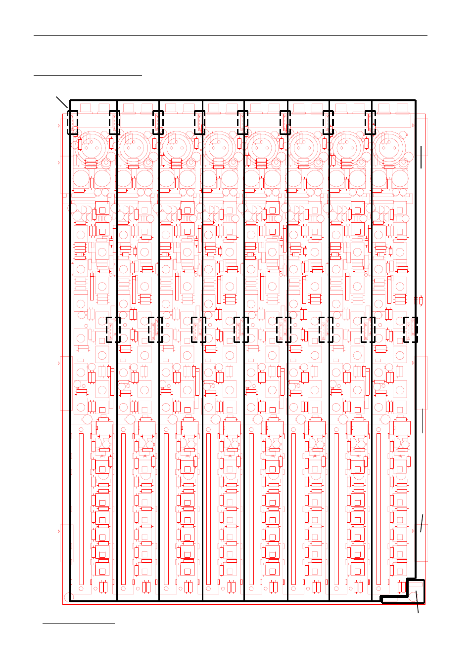
GS1 EXPANDER CIRCUIT DIAGRAM PCB KEY & LINK OPTION POSITIONS
The areas outlined on the PCB correspond to the sheet number on the circuit diagram C2054. For a detailed PCB component
ident refer to the Expander PCB component layout on the following page
EX 8
EX 7
EX 1
EX 2
EX 3
EX 4
EX 5
EX 6
3
1
2
1+3
2+3
1+3
2+3
1+3
2+3
3
3
Sheet no:
*
3
*
Aux 1 link options:
Tape Return or Channel pre-fade
( 8 pairs)
Phantom Power link options
(PP or +48V)
( 8 off)
See also other documents in the category Allen&Heath Control panel:
- GL2800M SERVICE MANUAL (13 pages)
- GL2800M USER GUIDE (23 pages)
- 21 Series (18 pages)
- GL3800 (44 pages)
- Xone V6 (42 pages)
- Xone S6 (42 pages)
- Xone DX (67 pages)
- Xone 3D (42 pages)
- Xone 32 (25 pages)
- Xone 1D (2 pages)
- Xone 2D (34 pages)
- XB 14 (40 pages)
- WZ20 8 2 SERVICE MANUAL (35 pages)
- WZ16 2DX (28 pages)
- WZ16 2 (16 pages)
- WZ14-4-2 MK2 (24 pages)
- WZ14-4-2 (21 pages)
- WZ 20S USER GUIDE (35 pages)
- WZ 20S SERVICE MANUAL (23 pages)
- SR Plus OWNER MANUAL (1 page)
- Scepter SERVICE MANUAL (21 pages)
- Scepter USER GUIDE (42 pages)
- RPS9 (7 pages)
- RPS14 (18 pages)
- RPS10 (7 pages)
- ML5000 SERVICE MANUAL (135 pages)
- ML5000 SIDECAR USER GUIDE (4 pages)
- ML5000 USER GUIDE (60 pages)
- ML4000 USER GUIDE (4 pages)
- ML4000 USER GUIDE (56 pages)
- ML4000 SERVICE MANUAL (91 pages)
- ML3000 Application Guide (2 pages)
- ML3000 USER GUIDE (48 pages)
- ML3000 Using Guide (2 pages)
- ML3000 VCA (3 pages)
- MixWizard3 16-2 (30 pages)
- MixWizard3 14-4-2 (27 pages)
- MixWizard3 12M (22 pages)
- GS3000 (40 pages)
- GS1 USER GUIDE (22 pages)
- GR8A (11 pages)
- GR1 USER GUIDE (17 pages)
- GR1 SERVICE MANUAL (48 pages)
- GL4800 USER GUIDE (62 pages)