Servicing the master fader assembly – Allen&Heath ML5000 SERVICE MANUAL User Manual
Page 28
ML5000 Service Manual
27
Servicing the Master Fader assembly
Before beginning any service work, remove all power to the unit and disconnect any signal cables
where necessary. Ensure adequate lighting and use the correct tools.
Remove the numbered Ident strip by placing a flat headed screwdriver under one end and prizing it
upwards. Remove the Ident strip by ‘peeling’ it from one end of the console to the other.
Remove the 5x 6Bx3/8 Countersunk Pozi Zinc Screws from the top of the fader panel
(F) and the 5x
6Bx3/8 Flange Headed Pozi Black Screws from the bottom of the fader panel, taking care to retain the
plastic washers
(G) (see fig.4). Carefully tilt the fader panel assembly out from the console and
remove all connecting IDC wireforms. The fader panel assembly can now be removed from the
console.
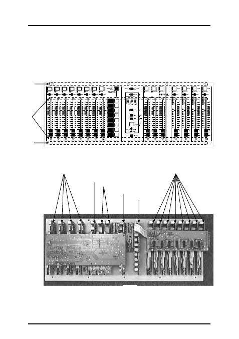
Flip the fader panel over to reveal the PCB assemblies (see fig.5).
Stereo Fader PCBs
Master Fader Centre PCB
Master Fader L/R PCBs
Mute Group PCB
VCA Master Fader PCBs
Control Panel PCB
Stereo Slave PCB
VCA Master Slave PCB
fig.5
fig.4
G
H
F