4 – how to sample the rpm signal, 1 – sampling the rpm via can bus/rs232, 2 – pre-condition to sample the rpm in another way – AiM MXL User Manual
Page 11
MXL
User manual
Release 1.24
2 0
2.4 – How to sample the RPM signal
MXL can sample the RPM signal in different ways:
• from the ECU via CAN bus or RS232;
• from the ECU through a square wave signal (from 8 to 50 V);
• from the coil: low voltage input (from 150 o 450 V).
3 0
2.4.1 – Sampling the RPM via CAN bus/RS232
To sample RPM via CAN bus/RS232 refer to ECU connection chapter.
3 1
2.4.2 – Pre-condition to sample the RPM in another way
To sample RPM signal from the ECU through a square wave signal or through the
coil it is necessary:
• MXL Strada + kit basic sensors (optional – part number X10MXLKS00000;
draw code 04.554.02);
• MXL Pista standard kit;
• MXL Pro05 + 22 pins Deutsch type connector wiring (optional – part number
V02554540; draw code 04.554.24) + 37 pins Deutsch type connector wiring
(optional – part number V02554240; draw code 04.554.20).
3 2
2.4.3 – Sampling the RPM from the ECU through a square wave signal
To sample the RPM from the ECU using a square wave, connect:
• the white cable labelled “RPM” (MXL Strada/Pista) of the logger wiring to the
ECU RPM signal;
• the blue cable labelled “RPM 8-50 V” of the 37 pins Deutsch type connector
wiring (MXL Pro05) to the ECU RPM signal.
Always refer to the ECU user manual for further information. In case ECU output
signal is not a steady square wave, an RPM adaptor (optional) is needed. To connect
the filter, follow this procedure.
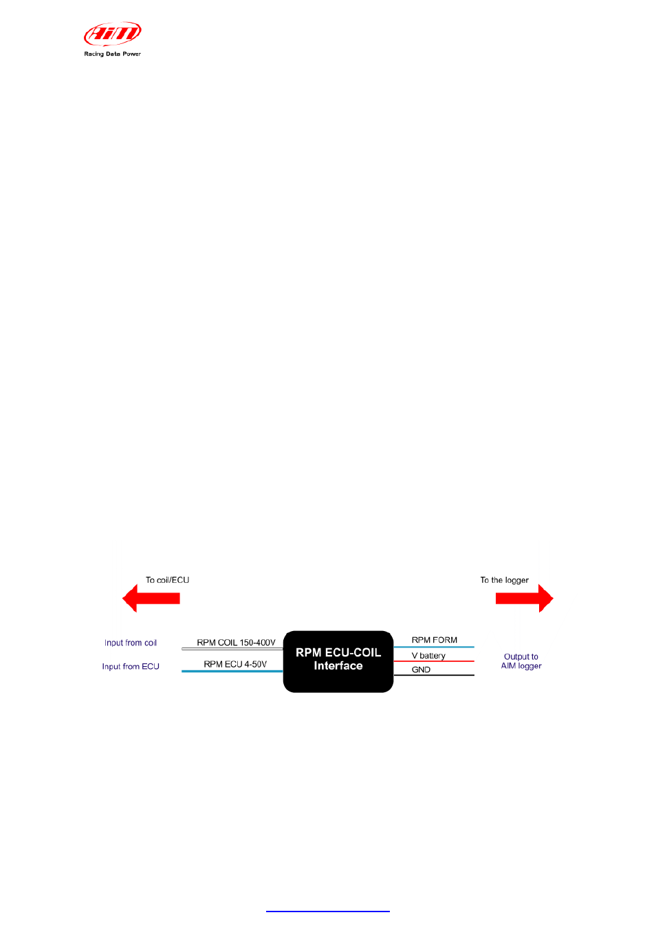
• Connect the blue cable labelled “RPM form” to the cable labelled “RPM” of
MXL Strada/Pista wiring.
• Connect the blue adapter cable, labelled “RPM form” to the blue cable labelled
“RPM 8-50V” of MXL Pro05 wiring – pin 12 of 37 pins Deutsch type connector.
• Connect the red interface cable labelled “V battery” to positive pole of the
vehicle battery. It is suggested to connect the red cable downstream the
vehicle master switch.
www.aim-sportline.com
10