Power supply connection – 2N VoiceBlue Next v3.4 User Manual
Page 20
20
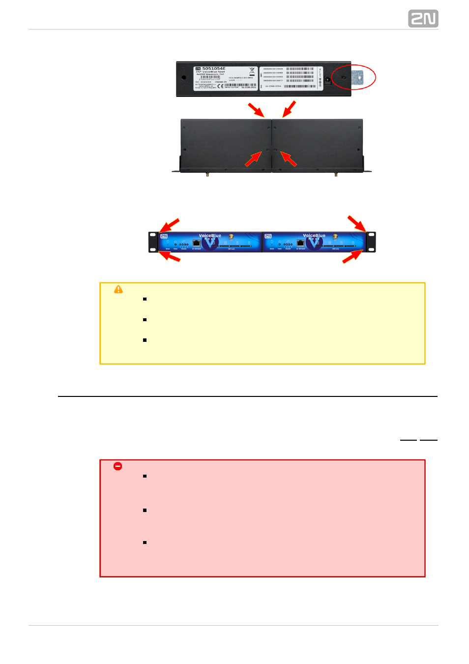
2.
3. Place the GSM gateway pair into a free 1U place in the system rack and fit it with
four rack screws (included in the package).
Caution
The rear and upper connecting plates have different holes – the
upper plate holes are larger and without threading.
Make sure that the plate does not get into the device to avoid
electric short-circuit inside the GSM gateway.
Leave 2 cm free space at least over and under the GSM gateway
for better ventilation (airflow)!
Power Supply Connection
Use only the power supply adapter included, or, with the power over Ethernet, a
certified PoE adapter to feed the gateway. Make sure that the electric distribution
network voltage is in compliance with the data on the supply adapter plate before
plugging the adapter. First plug the supply adapter into the mains socket and
only then
connect the adapter connector to the gateway. Refer to the status indicators.
Warning
Connecting a defective or inappropriate power supply adapter
may lead to a temporary or permanent 2N VoiceBlue Next
®
error!
Never connect
using the PoE and a local
2N VoiceBlue Next
®
adapter at the same time to avoid permanent 2N VoiceBlue
®
malfunction!
Next
Check whether the antenna is connected before plugging the
adapter. Feeding the device without antenna connection
may result in the GSM module transmitter damage.