Omega lite installation manual – 2N Omega Series - Instalation Manual User Manual
Page 19
2N
®
- OMEGA Lite
Installation manual
Installation manual
19
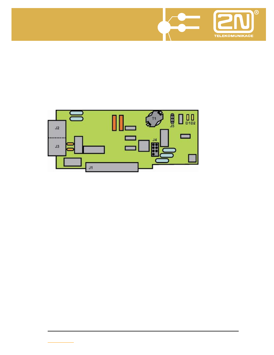
5.3. Module 1x external line / 1x internal line (order No 1880031)
Combined module for connecting one analogue external (J2) and one analogue
internal line (J3). The module allows the receipt of caller identification (Caller ID –
CLIP) using FSK modulation.
In the event of a power failure of the PBX, the module is equipped with a spill
relay which ensures the direct connection of the analogue external line to the
internal.
J1
- connector for connecting to motherboard (or extender module (the
connector is secured against incorrect connection by the blanking of
PIN 5,6,7,8).
J2
- connector RJ-45 (PIN 4-5) for connecting analogue external line.
J3
- connector RJ-45 (PIN 4-5) for connecting analogue internal line.
J4
- company servicing reanimation connector (SW for ALTERA).
J5
- connector for setting impedance (1-2= ETSI, 2-3= 600
Ω).
D1
- signalling LED ( picking up, ringing – external line).
D2
- signalling LED (picking up, ringing – internal line).
T1
-CO transformer
Note:
•
Equipment attached to connector J3 (telephone) must comply with the requirements
(standard – type approval) for equipment connected to the unified telephone system.