Assembly – Echo 72928 Owners Manual v.2 User Manual
Page 8
5
S
E C T I O N
2
Assembly
Torque Chart
Standard minimum tightening
torque for normal assembly
applications.
Bolts (SAE GR5)
Size
Ft. Lbs.
5/16"
20
3/8"
35
1/2"
75
5/8"
90
Screws
Size
Ft. Lbs.
5/16" Set
15
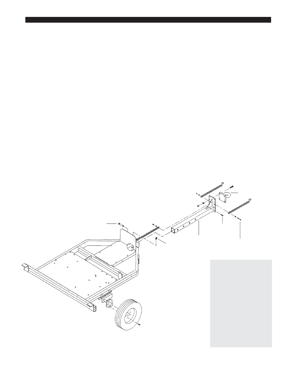
Top Link Pin
3/8" x 2"
Bolt
3/8" x 2-1/2"
Bolt
Lynch Pin
Adjustable
Hitch
Weldment
Pintle Eye
Figure 2.1
2.1.2 Attach the Pintle Hitch
1. Insert the adjustable hitch into the hitch opening in
the chipper trailer. Insert a 3/8" x 2" bolt through
the bolt hole in the adjustable hitch as shown in
figure 2.1. Place the end link in the safety chain
welded to the chipper trailer over the 3/8" bolt end.
Secure the chain with a washer and nut.
2. Attach the pintle hitch eye to the adjustable hitch
with 5/8" x 2" bolts, washers, and nuts. Torque the
bolts to 90 ft. lbs.
3. Connect the safety chains to the adjustable hitch
weldment as shown in figure 2.1. Use a 3/8" x
2-1/2" bolt, washers, and nut to attach the two
safety chains with hooks as shown.
4. Push the top link pin through the holes in the hitch
and trailer. Secure the top link pin with a lynch pin.
Adjust the hitch to make the chipper trailer as level as
possible when connected to the towing vehicle.
Your chipper may arrive totally or partially assembled.
If your chipper arrives partially assembled, you may
need to perform the steps in this section.
2.1.1 Attach the Trailer Wheels
1. Remove the chipper from its shipping crate. Place
the unit on a level surface before attempting to
assemble it. See the Torque Chart at the bottom of
this page for minimum tightening torque of bolts
and screws.
2. Raise the trailer several inches from the ground
with a hoist or jack. Make sure that the chipper is
supported securely.
3. Hold one wheel up to a hub and align the wheel lug
holes with the hub lug holes (see figure 2.1). Thread
the lug bolts into the holes and tighten the lug bolts
to 75 ft lbs. Follow a star pattern when tightening
the lug bolts. Repeat this step for the remaining
wheel.