Echo 72928 Owners Manual v.2 User Manual
Page 16
13
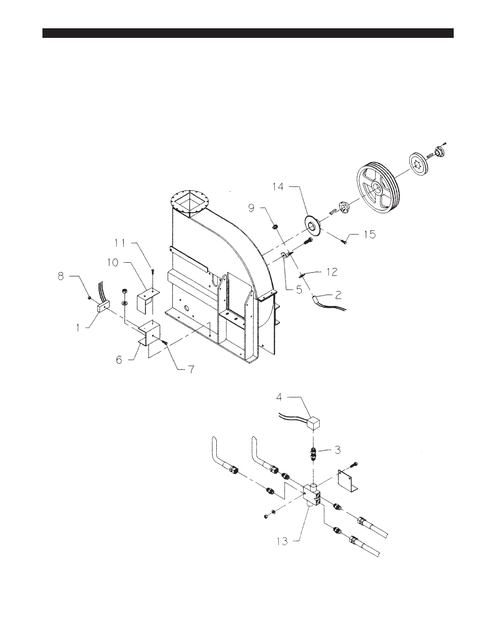
Electronic Feed Sensor:Installation Instructions for
Models 928 & 942
10. Mount the speed switch bracket to the center bolt
in the chipper base.(Ref #6)
11. Replace the crossover relief valve with the new
valve suppled with the valve kit. (Serial number
less than 19317 only)(Ref #3)
12. Remove outer and inner plugs
from the relief valve. Install
the soliniod cartridge valve and
coil so that the wires lead
down.(Metal side of
valve coil towards relief
valve).
13. Connect the solenoid
valve and sensor to the
speed switch and attach
the ground wires to the
frame. Route positive to
engine. (See wiring
diagram)(Ref #4)
14. Mount speed switch
and route wires according
to wiring diagram.
15. Attach cover over
speed switch with two
self tapping screws.
16. Replace the belt
guard.
17. Attach the chipper to
the tow vehicle.
1. Remove belt guard.
*If serial number is equal to or greater to 19317 skip
to step 9.
2. Losen hydraulic pump mount and remove pump
drive belt.
3. Remove chipper drive belt.
4. Remove the pump and chipper-driven pulley from
the rotor shaft.
5. Replace collar, shown below, with
the sprocket and collar
weldment supplied with the
valve kit.
6. Replace the chipper-driven
pulley and
pump pulley.
Note: To maintain the chipper rotor
position, push the chipper pulley bushing
tight against the collar and the collar tight
against the rotor bearing before tightening.
7. Replace the chipper drive belt.
8. Replace the pump drive belt, position the
pump to tension the belt, and tighten the
pump mount.
9. Attach the sensor and bracket under one of
the rotor bearing bolts so that it lines up with
the sprocket teeth.(Pickup should be approxi-
mately .020" from the teeth of the sprocket.
See Figure 1.)
S
E C T I O N
2