Echo 72928 Owners Manual v.2 User Manual
Page 10
7
S
E C T I O N
2
Detent
Ball
Clevis
Assembly
Nut
Insert cable
through hole
Feed
Control
Lever
Cable
Anchor
Weldment
Hydrostat
Control
Cable
Blower Discharge Tube
Mounting Clamp
Mounting Flange
Forward
Detent
Figure 2.4
Figure 2.5
▲
Clevis Assembly
Chipper Chute
Neutral
Detent
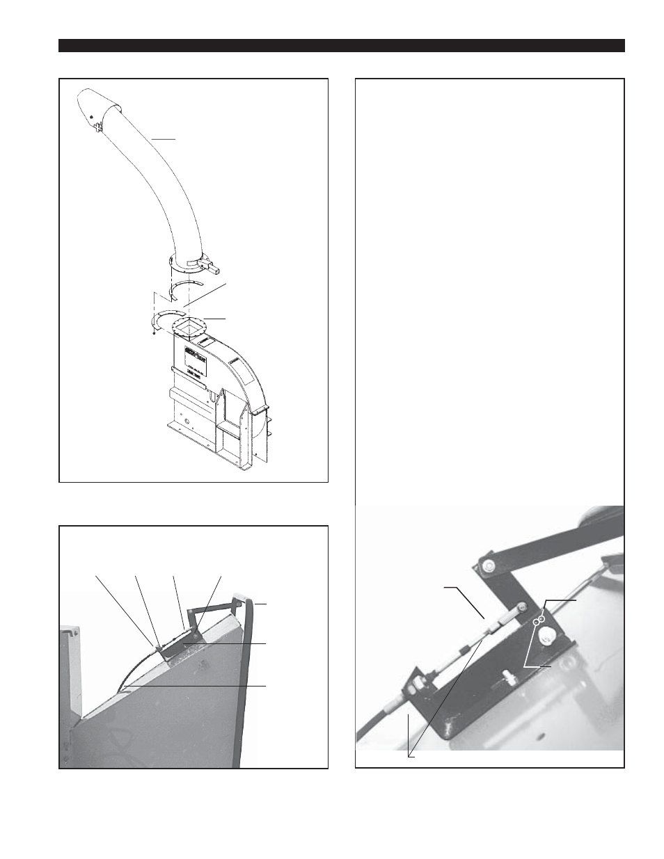
2.1.7 Adjusting the Hydraulic
Feed Control Cable
Figure 2.6 shows the hydraulic feed control cable
assembly and the detent position slots. The cable
is attached and adjusted from the factory, but it
should be checked and adjusted as needed before
use. The hydraulic feed control lever has three
positions:
Forward (lever moved toward the operator)
Neutral (lever in center position)
Reverse (lever moved away from operator;
reverse has no detent position)
When the operator moves the control lever to the
neutral position, the detent ball should be
positioned in the rear detent slot (see figure 2.6).
The feed roller should come to a complete stop
when the control lever is in the neutral position. If
it does not stop, adjust the clevis assembly on the
control cable as follows:
1. If the control lever is in neutral and the roller
creeps forward, the cable is too short; adjust it
to a longer length.
2. If the roller creeps in a reverse direction, the
cable is too long; adjust it to a shorter length.
3. Adjust the cable as needed to
compensate for cable stretch.
▲
Adjust cable here as needed.
Figure 2.6