Warning, 7 clearing a plugged rotor, 8 repairing or replacing ro- tor bearings – Echo 74824 Owners Manual v.3 User Manual
Page 19: 6 adjusting drive belts
Page 17
6" & 8" Bear Cat Chipper Operator’s Manual
5.7 CLEARING A PLUGGED ROTOR
Feeding too large or too much chipable material at once
may plug the chipper. To clear a plugged rotor, proceed as
follows:
1.
Depress foot clutch pedal and turn off engine key switch.
Release foot clutch pedal when engine is stopped.
2.
Remove the two 3/8" retaining bolts holding the access
cover to the main frame assembly.
WARNING
If the machine becomes plugged, depress the foot clutch
pedal, shut off the engine, disconnect the spark plug wire
and allow the machine to come to a complete stop before
clearing debris. Do not operate the machine without proper
guards and shields in place.
5.8 REPAIRING OR REPLACING RO-
TOR BEARINGS
1.
Remove the two 3/8 inch retaining bolts holding the ac-
cess cover to the main frame assembly. Tilt access
cover over to allow access to rotor.
2.
Remove large belt guard (three 5/16 inch bolts).
3.
On hydraulic feed units, loosen bolts that anchor the
hydraulic pump to mount and remove hydraulic belts.
4.
Step down on foot clutch pedal to release tension and
remove drive belt from pulleys.
5.
Using the push bolts from the bushing, remove the bush-
ing and pulley from the rotor shaft.
6.
If a rotor bearing needs repair, it is best to remove the
complete rotor assembly from the chipper frame.
7.
Using an overhead hoist or lifting device, remove the
four 1/2 inch bolts on each rotor bearing and lift the rotor
assembly completely out of the frame. The complete
rotor assembly weighs 275 lbs.
8.
Once the rotor assembly is out of the frame, both bear-
ings on the rotor assembly shaft can be removed by a
puller and replaced.
9.
Use the overhead hoist or a lifting device to return the
complete rotor assembly to the chipper frame.
SERVICE & MAINTENANCE
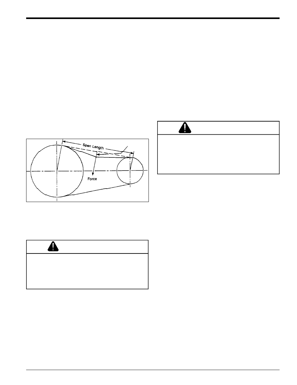
5.6 ADJUSTING DRIVE BELTS
1.
Depress foot clutch pedal. Shut engine off and discon-
nect battery cables.
2.
Remove large belt guard (three 5/16 inch bolts).
3.
Adjust the eyebolt that anchors the idler spring to ad-
just belt tension. Tighten the eyebolt until the belt de-
flection at the center of the belt is 7/16" when a 20 lb.
load is placed against the belt (see Figure 5.4).
4.
Replace belt guard.
5.
Start engine, release foot clutch pedal to engage belt,
and test unit. Readjust pulleys and belt tension if needed.
To adjust the drive belt tension, proceed as follows:
Figure 5.4 - Drive Belt Tension
3.
Lift up rotor access cover.
4.
Clean the debris out the chipper rotor. Turn the rotor by
hand to be sure it is free to rotate. Be careful to avoid
the chipper blades when cleaning out the debris.
5.
Close rotor access cover and replace bolts.
6.
Depress foot clutch pedal, and start the engine. Re-
lease the foot clutch pedal when engine is running to
engage drive belt. Resume operation.
WARNING
The rotor assembly has a lock mechanism (see Figure
5.1). When working on the rotor assembly, use the lock
mechanism at all times. There is a hole in the rotor jack
shaft and a matching hole in the bracket mounted to the
rotor bearing front side. Install a punch through the rotor
shaft and bracket to lock the rotor in place.
Refer to Figure 5.5 while repairing or replacing rotor bearings.
7/16" Deflection