Service & maintenance 5, Warning – Echo 74824 Owners Manual v.3 User Manual
Page 17
Page 15
6" & 8" Bear Cat Chipper Operator’s Manual
5.2 SHARPENING CHIPPER BLADES
When the chipper blades dull, chipping becomes difficult. It
is recommended that the chipper blades are sharpened every
5-15 hours of chipper operation.
Use the following procedure to remove the chipping blades
for sharpening:
1.
Remove the two 3/8 inch retaining bolts holding the ac-
cess cover to the main frame assembly.
2.
Tilt access cover over to allow access to rotor. Rotate
the rotor so that the bolts holding the chipper blades
are most accessible.
3.
Install the rotor (disk) lock (see Section 5.1). The disk
is now restrained for removing the blades. To access
the remaining blades, remove the punch or screwdriver
and reposition disk. Return the punch or screwdriver to
the rotor lock hole.
4.
Remove the two hex head bolts holding the blade to the
rotor.
NOTE
The chipper blades consist of two edges (see Figure 5.2).
When the first edge dulls, flip the blade and torque to 75
Ft-lb to use the second sharp edge. Repeat this procedure
for each blade. After both edges are dull, sharpen the
chipper blades.
WARNING
Before inspecting or servicing any part of the machine,
shut off the power source, disconnect the spark plug wire
from the spark plug and make sure all moving parts have
come to a complete stop. The chipping blades are sharp!
Use care when working on machine to avoid injury.
S e c t i o n
Service & Maintenance
5
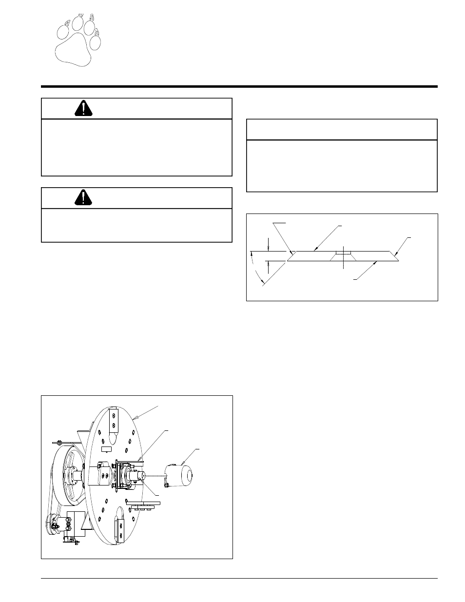
5.1 INSTALLING THE ROTOR (DISK)
LOCK
When working on the rotor (disk) assembly, use the lock
mechanism at all times (see Figure 5.1). Follow the steps
below to install the rotor lock:
1.
Remove the plastic rotor shaft cover under the chipper
chute. There is a hole in the rotor jack shaft and a match-
ing hole in the bracket mounted to the rotor bearing
frontside.
2.
Install a punch or screwdriver into the rotor shaft and
bracket to lock the rotor in place.
WARNING
The rotor (disk) assembly has a lock mechanism. When
working on the rotor assembly, use the lock mechanism
at all times.
Figure 5.2 - Chipper Blade Surfaces
45°
.38
MOUNTING SURFACE
DO NOT GRIND
MOUNTING SURFACE
DO NOT GRIND
SHARPENED
SURFACE
SHARPENED
SURFACE
Figure 5.1 - Rotor (Disk) Lock
ROTOR LOCK HOLE.
ROTOR SHAFT CAP
MATCHING HOLE IN BRACKET
ROTOR (DISK) ASSEMBLY