4 setting chipper blade clearance, 5 replacing drive belts, 3 replacing chipper blades – Echo 74824 Owners Manual v.3 User Manual
Page 18
Page 16
6" & 8" Bear Cat Chipper Operator’s Manual
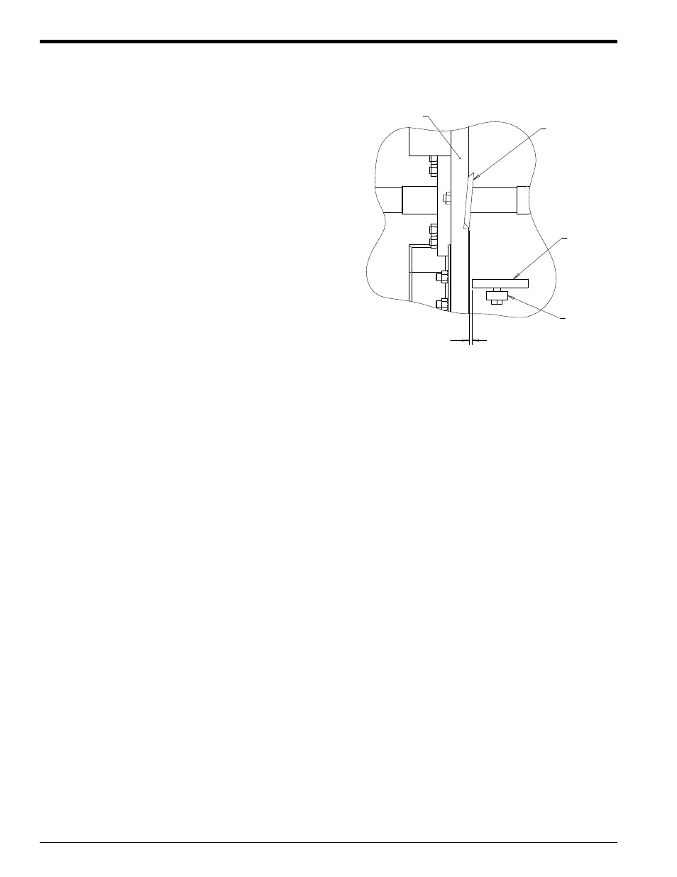
The chipping blades should clear the chipper block located
directly under the chipper chute by 1/16 inch. To adjust the
blade clearance, proceed as follows:
1.
Lift rotor access cover and expose rotor. Loosen the
three 1/2 inch bolts that hold the chipper anvil to the
frame (see Figure 5.3).
2.
Measure the amount of clearance between chipping
blades and chipping anvil from inside of housing. Adjust
inward or outward to desired measurement.
3.
Check clearance on all the blades.
4.
Tighten bolts on chipping anvil to 75 Ft-lb and resume
operation.
5.4 SETTING CHIPPER BLADE
CLEARANCE
1.
Remove large belt guard (three 5/16" bolts).
2.
Loosen bolts on hydraulic pump and remove the hy-
draulic pump belt, if equipped.
3.
To remove old drive belt, step down on foot clutch pedal
to take tension off belt. Remove old belt from pulleys.
4.
Install new drive belt on pulleys. Check alignment of
pulleys and adjust if needed. Release foot clutch pedal.
5.
Adjust the drive belt tension until the belt deflection at
the center of the belt is 7/16" when a 20 lb. load is
placed against the belt (see Section 5.5)
6.
Replace hydraulic pump belt, if equipped. Readjust hy-
draulic pump belt tension by sliding the hydraulic pump
in the mounting slots. Tighten bolts.
7.
Replace belt guard.
8.
Depress foot clutch pedal, start engine, release foot
clutch pedal to engage belt, and test unit. Readjust
pulleys and belt tension if needed.
5.5 REPLACING DRIVE BELTS
Check the condition of the drive belt annually or after every
30 hours of operation, whichever comes first. If the belt is
cracked, frayed, worn, or stretched, replace it. Only replace
belt with original banded type belt. Do not use single type
belts. Follow the procedure below to replace the drive belt.
SERVICE & MAINTENANCE
1.
Remove the two 3/8 inch retaining bolts holding the ac-
cess cover to the mainframe assembly.
2.
Tilt access cover over to allow access to rotor. Rotate
the rotor so that the bolts holding the chipper blades
are most accessible.
3.
Lock rotor assembly (see Figure 5.1).
4.
Remove the two hex head bolts holding the blade to the
rotor.
5.
Remove old blade, install new blade and torque to 75
Ft-lb. Repeat this procedure for each blade.
5.3 REPLACING CHIPPER BLADES
If the chipper blade does not extend beyond the edge of the
rotor chipping slot, follow the procedure below to replace
the chipper blade.
1/16" - 1/8"
ANVIL
CHIPPER
BLADE
ROTOR
ANVIL
SPACER
If chipping anvil edge is damaged or worn unevenly, remove
the three bolts holding the anvil and use one of the other
three edges. Adjust for correct measurement.
Figure 5.3 - Chipper Blade/Anvil Clearance
5.
When sharpening the blades be sure to maintain the
original 45 degree angle. Be careful when grinding so
that the blade material does not get too hot and change
color. This will remove the blade's special heat treated
properties. Use short grinding times and cool with wa-
ter. Try to remove an equal amount off each blade to
maintain balance.
6.
Reinstall blade and torque to 75 Ft-lb. Repeat this pro-
cedure for each blade.
(DISK)