9 chipping guide, 8 chipper feed controller – Echo 7812086 Owners Manual v.2 User Manual
Page 16
Bear Cat Owners Manual
12
OPERATION
4.9 CHIPPING GUIDE
The Bear Cat chips a variety of materials into a more readily
decomposed or handled condition. The following guidelines can
help you get started.
Run unit at full operating speed before starting to chip
material.
Select limbs that are up to 12 inches in diameter. Trim side
branches that cannot be bent enough to feed into the feed
chute. Hold small diameter branches together in a bundle
and feed in simultaneously.
Using the feed roller lift makes feeding larger logs (8" and
above) easier and prevents the banging and slamming to
the top that can occur.
Exclude pieces of metal, rocks, bottles, cans, and other
foreign objects when feeding chipable material into the
machine.
Feed brush from the side of the feed chute, rather than from
the front. Step aside to avoid being hit by the brush moving
into the chipper.
Do not lean over the feed chute to push objects into the cut-
ting device. Use a push stick or brush paddle.
Never use shovels or forks to feed brush. They can be
chipped, are expensive to replace, and cause extensive
damage. In addition, metal pieces can be ejected from the
feed chute and cause serious injury or death.
Never feed brush into the feed chute with your feet.
Place limb, butt end first, into the feed chute until it contacts
the feed roller. The actual feed rate of the limb into the chip-
per will depend on the type of material fed and sharpness
of the cutting blades.
Stop the material feeding and allow the engine to recover if
the engine slows to where it may stall.
Remove the branch and rotate it before reinserting it into the
chute if the chipper jams.
Alternately insert and retract the limb or insert continuously
at a rate that will not kill the engine.
Chipping dead, dry material will create heat and dull the
chipping blades quickly.
Alternate green material with dry material to lubricate the
chipping blades for longer life and better performance.
The chipping blades will become dull and will require periodic
sharpening. Refer to the Service and Maintenance section
for sharpening instructions.
1.
2.
3.
4.
5.
6.
7.
8.
9.
10.
11.
12.
13.
14.
15.
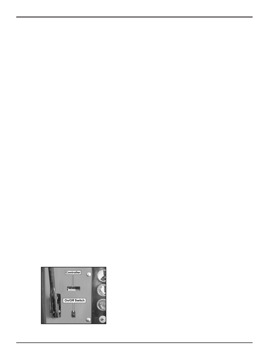
4.8 CHIPPER FEED CONTROLLER
The chipper is equipped with a pre-programmed feed controller.
The controller is located next to the control panel (Figure 4.7).
The controller serves a variety of functions including monitoring
chipper rotor RPM, controlling the feed roller, and providing
routine maintenance alerts. The controller has an on/off switch
located next to the control panel (Figure 4.7). If the controller
becomes damaged, the chipper will still run with the controller
shut off, however all of the controller functions will be disabled.
The control bar located on the feed chute will control the feed
roller.
The controller functions are further detailed below:
The controller operates the feed roller. The controller moni-
tors the RPMs of the chipper rotor and if it drops below the
preset range the feed roller stops. When the RPMs reach
an acceptable level, the feed roller will reengage.
The controller also has a “try again” feature. The controller
monitors the hydraulic pressure of the feed roller. If it senses
the level is too high (the feed roller becomes obstructed) the
controller will reverse the feed roller , removing the material
trying to be chipped. The controller will then engage the roller
into the forward position and try to feed the material again. If
this cycle continues, remove the obstruction manually. Trim
or reposition material if necessary.
At start up, the PWR/ERR LED on the controller will remain
off for 3 seconds, after which it will display either error codes
or power supply status. If error codes are present, the LED
will blink accordingly. If no error codes are present, the
power supply status is displayed:
100 Hour Service Error Code: Will blink every 100
hours of operation (blinks 10 times).
Blade Maintenance Error Code: Will blink every 15
hours of operation (blinks 5 times).
Power Supply Status Mode: ON (power ok), OFF
(low or no power), blinking once a second (power
above +30Vdc).
To reset service alerts, locate light green wire in engine
compartment next to the hour meter. Connect green wire
to red wire connector for five seconds.
NOTE: The RPM sensor on the rotor must flash or the controller
won’t work. Clearance between the sensor and the bolt must be
between 1/32” and 3/32”.
1.
2.
3.
•
•
•
4.
Figure 4.7 - Chipper Feed Controller