2 assembly ce compliant, English – Echo CH4400 Owners Manual v.2 User Manual
Page 11
4 INCH CHIPPER
7
ENGLISH
ASSEMBLY
2.2 ASSEMBLY CE COMPLIANT
19
1
5
6
7
9
14
15
17
1. Mount the wheels to the axle as described in step 1
of Section 2.1
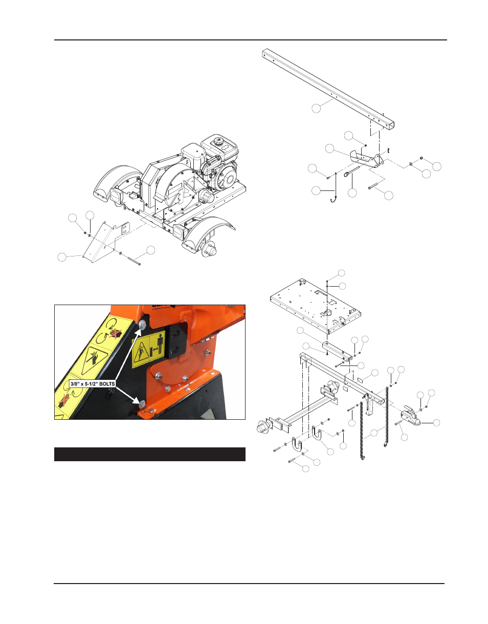
2. Attach the jack stand(17) to the hitch pole(19), as shown
in Figure 2.5, using 3/8 x 3" bolt(7), 3/8 flat washer(9)
and nylock nut(10). Attach the nylon lanyard(1) to the
jack stand(17) using 1/4 x 3/4" bolt(6) and 1/4 nylock
nut. Swing jack stand(17) up into the stored position
and secure by using the hitch pin(5) and cotter pin.
11
18
6
1
Figure 2.6, CE Compliant hitch
Figure 2.4, Standard configuration discharge cap.
3. Place hitch pole channel(18) in position underneath
trailer deck at position for standard configuration and
mount to trailer deck using two 3/8 x 1" bolts(12), 3/8
flat washers(9) and nylock nuts(15).
Figure 2.5 Discharge cap
2
3
4
8
9
9
9
10
10
11
11
12
13
13
15
15
15
16
18
20
6. Move the chipper deflector weldment located inside
the chipper housing to the down position (Figure 2.3).
7. Place discharge cap assembly(18) onto the housing
by aligning the bolt holes of the discharge cap(18) and
the bolt holes in the housing. Make sure the discharge
cap is in the proper position and place the two 3/8 x 5
1/2" bolts(1) through the bolt holes. Secure by adding
3/8 flat washers(6) and nylock nuts(11) to the 3/8 x 5
1/2" bolts(1).
4. Now, insert hitch pole assembly into the mounted hitch
pole channel(18) making sure the end of the hitch pole
reaches the axle. Temporarily secure the hitch pole
assembly in place using two 3/8 x 3 1/4" bolts(16), four
3/8 washers(9) and two 3/8 centerlock nuts(11) through
the aligned mounting holes of the hitch pole channel(18)
and the hitch pole. (Do not tighten hardware securely
until step 5 is complete.)
Figure 2.7, Exploded view illustration for
assembly demonstration purposes