Echo CH5540HXE User Manual
Page 7
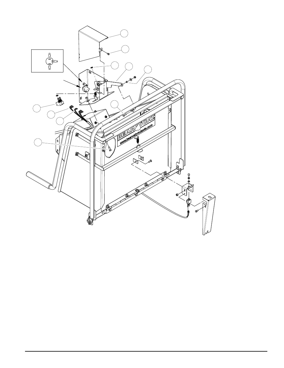
Instruction Sheet
COMPLETE
CIRCUIT
WHT
RED/YEL
RED/GRN
TRI-COLOR LED
1
2
3
4
5
6
7
8
9
10
KIT # 77540-00 FoR ModEl: Ch5540hxE
SWITCh Box REMovAl
1. remove control box cover (2) by removing
serrated flange bolts (3).
2. remove mechanical switches (4) by
removing inside nut (5) closest to the control
arm. note from which position each switch
came from they will need to be installed in
the same holes during installation of new
control box.
3. remove wires from the back of the reset
switch (7) and tri-color led (6).
4. remove bolt (8) connecting control arm to
switch control bar.
5. remove two hex bolt (10) connecting switch
box (1) to chipper chute.
SWITCh Box INSTAllATIoN
1. mount new switch box (1)
to top of chipper chute
with two hex bolts (10),
washers, and nuts. ensure
switch box is all the to the
front of the machine in
the slot before tightening
completely
2. connect control arm to
switch control bar using
bolt (8), spacer, washer,
and nut. ensure spacer (9)
is in the switch control bar
before tightening.
3. install tri-color led into
control box so that the
silver terminal is located at
the three o'clock position
from the inside of the box.
6. connect wires to the back of the reset switch
(7) and tri-color led (6). ensure wires for
the tri-color led are connected as shown in
diagram.
7. install mechanical switches (4) into control
box (1) using the nuts (5) previously
removed. ensure that switches are put into
the same hole that they came out of. ensure
not to overtighten damage to switch may
occur.
8. install control box cover (2) on control box (1)
using serrated flange bolts (3).