Echo CH5540HXE User Manual
Page 6
Instruction Sheet
COMPLETE
CIRCUIT
WHT
RED/YEL
RED/GRN
TRI-COLOR LED
1
2
3
4
5
6
7
8
1
2
3
4
5
6
7
8
9
10
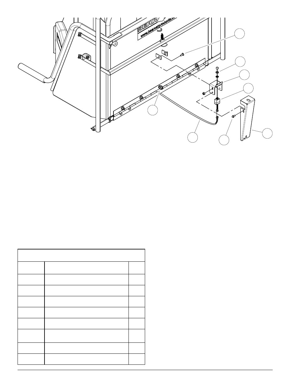
KNEE BAR SWITCh REMovAl
1. remove the two screws (2) and loosen the
nut (3) at the bottom of the knee bar switch
cover (1) and remove it.
2. remove plunger switch (4) from switch
bracket by removing plunger nut.
disconnect plunger switch from harness
(7) by removing the two screws connecting
them
3. remove switch bracket (6) from extension
tray by removing two carriage bolts (8).
PlUNGER SWITCh INSTAllATIoN
1. install new switch bracket (6) on to
extension tray using two carriage bolts
(8).
2. install new plunger switch (4) into
switch bracket using supplied plunger
nut (5), washer, and plunger.
3. cut off ring terminals from plunger end
of harness (7) and replace with supplied
female spade connectors. connect
harness to plunger switch (4).
4. using two screws (2) mount the new
switch cover (1) to switch bracket(6).
while installing adjust the new switch
cover so that it prevents the plunger
switch from bottoming out when the
knee bar is depressed.
5. adjust plunger switch (4) by loosening
the two carriage bolts (8) and setting
it so that it is activated when the knee
bar is depressed.
KIT, CoNTRol SWITChES, Part #77536-00
PART#
dESCRIPTIoN
QTY
14624-00
connector, 1/4 Qd female
2
14625-00
connector, 1/4 Qd male
2
15176
Scw,11/32*7/8 hwh ab thread Zp
2
15349
bolt,carr 5/16*7/8" Gr5 nc Zp
2
15904-00
nut, 5/16-18 nylock-flanGe
2
32375-00
Switch, momentary ip67 nor-
mally on
1
77527-00
aSSembly, Switch boX
1
77532-12
bracket, Switch
1