4 adjusting the chipper anvil, 5 lofa control programming – Echo CH9540H Owners Manual v.2 User Manual
Page 18
PTO CHIPPERS
14
SERVICE & MAINTENANCE
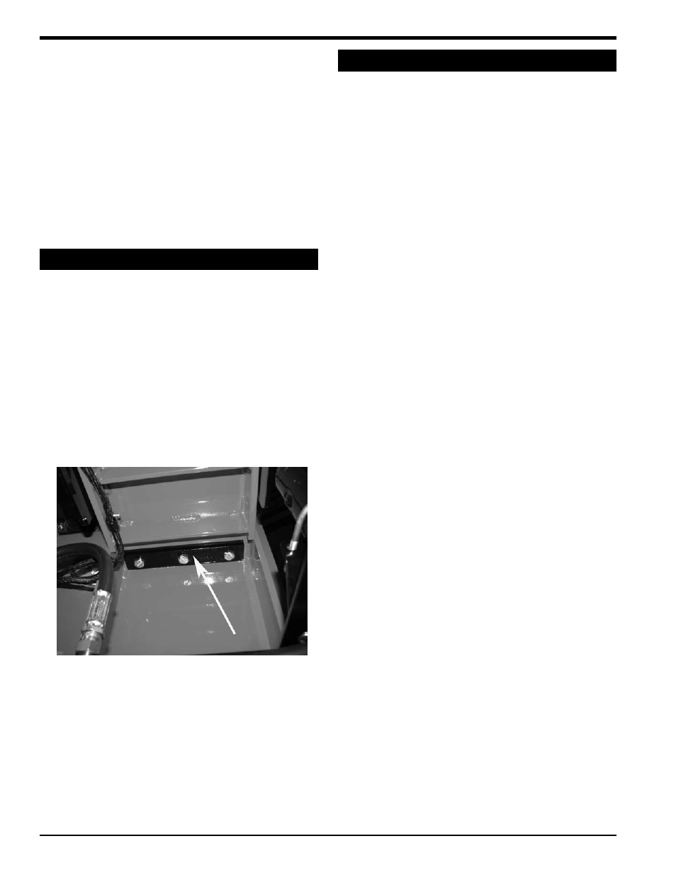
5.4 AdJuSTING THE CHIPPER ANvIL
Remove the two 3/8" bolts on the rotor access cover.
1.
lift rotor access cover and expose rotor.
2.
Measure the amount of clearance between chipping
3.
blade and chipping anvil from inside the housing.
loosen the three 1/2 inch bolts that hold the chipper
4.
anvil to the frame. The bolts are accessed underneath
the feed roller (see picture below).
Adjust anvil inward or outward to the correct clearance.
5.
check how all blades clear the anvil.
Tighten bolts on chipping anvil to 75 ft. lbs. and bolt
6.
rotor access cover closed.
If the chipping anvil edge is damaged or worn unevenly,
remove the three bolts holding the anvil and use one of the
other three edges. Adjust for correct measurement.
The chipping blades should clear the anvil by 1/16 inch to
1/8 inch. check the clearance every 8 hours of operation
and adjust if needed. The chipping anvil is reversible. All
four sides of the anvil can be used for chipping.
To adjust the anvil:
4. use short grinding times and cool with water or some
type of liquid coolant.
5. Remove an equal amount off each blade to maintain
rotor balance.
6. Small imperfections such as nicks and burrs on
the flat side of the blade will not affect the chipping
performance of the machine.
7. For blades that have been repeatedly sharpened,
ensure that the sharpened surface extends past the
chipping slot opening. If it does not extend past the
opening, the blades should be replaced.
5.5 LoFA CoNTRoL PRoGRAmmING
An electronic feed sensor is optional on the ch8540 and
standard on the chF9540h. To program the sensor, see
below.
STEP 1. INITIATING PRoGRAm modE
hold down the “S” button while turning the engine key to
the “on” position until “l” starts to flash on the lcd.
STEP 2. ENTER LoW (L = LoW) RPm
The low setting is the RPM speed where the feed roller
stops. The “up” arrow increases the RPM setting, while
the “down” arrow decreases the RPM setting. Setting the
speed lower causes the engine to lug down more before
the feed roller stops.
hold the appropriate (either up or down) arrow until
1.
the desired RPM speed is displayed (Recommended
1375 rpm).
Push the “S” button once with the desired RPM setting
2.
displayed to save. do not choose a setting equal to
or below zero.
STEP 3. ENTER NoRmAL
(N = NoRmAL) RPm
The normal setting is the RPM speed that the chipper rotor
usually rotates
hold the appropriate (either up or down) arrow until
1.
the desired RPM speed is displayed (Recommended
1500 rpm).
Push the “S” button once with the desired RPM setting
2.
displayed to save.
STEP 4. ENTER HIGH (H = HIGH) RPm
The high setting is not needed with this application.
Set to zero to deactivate.
1.
Push the “S” button once with zero displayed to save.
2.
STEP 5. ENTER RETuRN
(RET = RETuRN) RPm
The return setting is the RPM speed where the feed roller
restarts. The feed roller should restart before the rotor
reaches “normal” RPM to maximize chipper efficiency.
Setting the speed higher allows the engine to recover more
before the feed roller restarts.
hold the appropriate (either up or down) arrow until
1.
the desired RPM speed is displayed (Recommended
1400 rpm).
STEP 6. ENTER NumbER oF PoLES (IPu=NumbER
oF PoLES)
The number of poles is used to indicate the number of
speed pickup devices.
hold the appropriate (either up or down) arrow until
1.
(1) is displayed.
Push the "S" button once with one (1) displayed to save.
2.
Arrow points to chipper anvil